What this code means
P2097 can indicate that fuel trim after the catalyst is too rich.
What the vehicle may do
- The PCM may store this code when fuel trim deviates.
Possible fault areas
- Possible fault areas include the A/F control system components.
- The exhaust system may have leaks, clogs, or restrictions.
- The A/F Sensor (Sensor 1) may be at fault.
Diagnostic path
Understanding P2097
On this 2025 Honda Accord 1.5, P2097 means Post Catalyst Fuel Trim System Too Rich. In plain language, fuel trim after the catalyst may be too rich. Here is what this code tells us. The PCM may store this code when fuel trim deviates. Here are the main areas to check. Possible fault areas include the A/F control system components. The exhaust system may have leaks, clogs, or restrictions. The A/F Sensor (Sensor 1) may be at fault.
Before troubleshooting
Before you troubleshoot, review How to Troubleshoot.
Check related codes first
Troubleshoot any DTCs listed or indicated systems below first. - A/F Sensor (Sensor 1) \[PGM-FI\]: DTC P0130, P0133, P2195, P2237, P2238, P2243, P2245, P2251, P2252, P2A00 - A/F Sensor (Sensor 1) Heater \[PGM-FI\]: DTC P0134, P0135 - Secondary HO2S (Sensor 2) \[PGM-FI\]: DTC P0137, P0138, P0139, P2270, P2A01 - Secondary HO2S (Sensor 2) Heater \[PGM-FI\]: DTC P0141 - Fuel System \[PGM-FI\]: DTC P0171, P0172 - No. 1-No. 4 Cylinder Injector(s) \[PGM-FI\]: DTC P0201, P0202, P0203, P0204 - No. 1-No. 4 Cylinder Misfire \[PGM-FI\]: DTC P0300, P0301, P0302, P0303, P0304 - No. 1-No. 4 Cylinder Ignition Coil(s) \[PGM-FI\]: DTC P030A, P030D, P031A, P031D - No. 1 - No. 4 Cylinder A/F Variation \[PGM-FI\]: DTC P219C, P219D, P219E, P219F
Troubleshoot any DTCs listed or indicated systems below first. A/F Sensor (Sensor 1) \[PGM-FI\]: DTC P0130, P0133, P2195, P2237, P2238, P2243, P2245, P2251, P2252, P2A00 A/F Sensor (Sensor 1) Heater \[PGM-FI\]: DTC P0134, P0135 Secondary HO2S (Sensor 2) \[PGM-FI\]: DTC P0137, P0138, P0139, P2270, P2A01 Secondary HO2S (Sensor 2) Heater \[PGM-FI\]: DTC P0141 Fuel System \[PGM-FI\]: DTC P0171, P0172 No. 1-No. 4 Cylinder Injector(s) \[PGM-FI\]: DTC P0201, P0202, P0203, P0204 No. 1-No. 4 Cylinder Misfire \[PGM-FI\]: DTC P0300, P0301, P0302, P0303, P0304 No. 1-No. 4 Cylinder Ignition Coil(s) \[PGM-FI\]: DTC P030A, P030D, P031A, P031D No. 1 - No. 4 Cylinder A/F Variation \[PGM-FI\]: DTC P219C, P219D, P219E, P219F
Confirmation Procedure
Here is how the separate Confirmation Procedure works. Start the engine. With no load and the transmission in P or N, hold engine speed at 3,000 rpm. Keep it there until the radiator fan comes on. For the test-drive, use the diagnostic scanner (HDS) to check ECT Sensor 1. That reading must be above 158 °F (70 °C). The transmission must be in D. Drive at a steady speed between 15 - 75 mph (25 - 120 km/h) for 67 seconds or more. Then monitor the scanner's OBD STATUS (PGM-FI) for DTC P2096 and/or P2097.
Scanner functions
The scanner paths for these checks are PGM-FI > Function Test > CYLINDER A/F TEST and PGM-FI > Data List.
Cylinder A/F variation
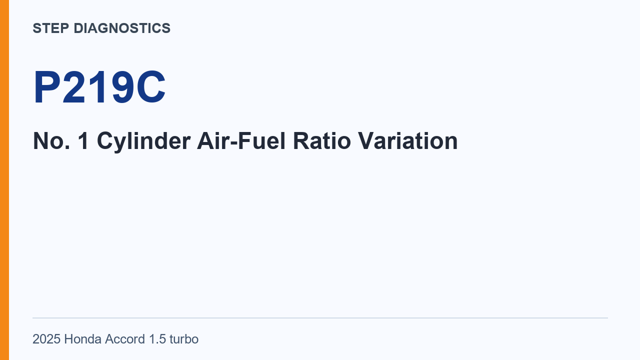
For the separate Cylinder A/F Variation Inspection, start the engine. With no load and the transmission in P or N, hold engine speed at 3,000 rpm. Keep it there until the radiator fan comes on. Turn the A/C off. Turn all electrical loads off. Then use the scanner's CYLINDER A/F TEST. The expected result is NORMAL. If the result is abnormal, troubleshoot DTC P219C, P219D, P219E, and P219F.
The CYLINDER A/F TEST is the inspection assigned to the A/F control system components. An abnormal result directs troubleshooting toward P219C, P219D, P219E, and P219F; it does not establish that A/F Sensor (Sensor 1) is the cause. A NORMAL result satisfies this inspection item, while the sensor conclusion still depends on the other inspection items also being normal.
Exhaust system check
The separate Exhaust System Visual Inspection checks for leaks, clogs, and restrictions. Inspect for exhaust leaks between the A/F sensor and Secondary HO2S (Sensor 2). Also inspect the exhaust system for any clogs or restrictions. The normal condition is no leaks, clogs, or restrictions. If this inspection is abnormal, there is a problem with exhaust system components.
The leak check and the clog or restriction check have different scopes. The leak check covers the section between A/F Sensor (Sensor 1) and Secondary HO2S (Sensor 2), while the clog or restriction check covers the exhaust system. No leak in that section alone is not enough for a normal inspection: clogs and restrictions must also be absent. An abnormal finding identifies the exhaust system components as a problem area.
A/F sensor assessment
The separate A/F Sensor (Sensor 1) Inspection gives a conditional conclusion. If the other inspection items show normal conditions, the remaining A/F sensor is determined to be the cause.
This is a conclusion by elimination, not a diagnosis made from P2097 alone. The stored code reflects a fuel-trim deviation; identifying A/F Sensor (Sensor 1) as the cause requires normal results from the other inspection items.
More diagnostic steps
For more diagnostic steps, visit stepdiagnostics.com.
Final check
The A/F sensor may be the cause when the other inspection items indicate normal conditions.
For more guided automotive diagnostics, visit STEP Diagnostics.