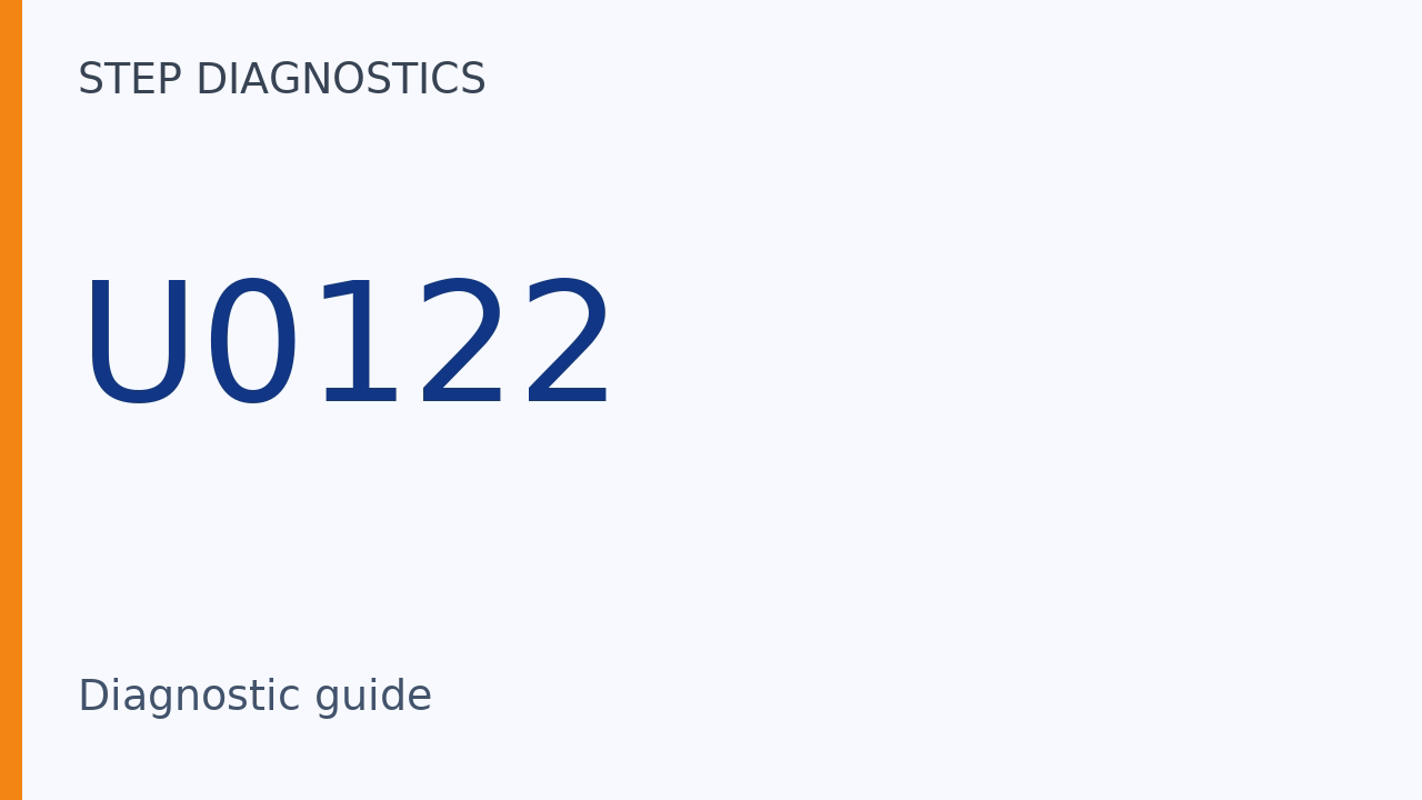
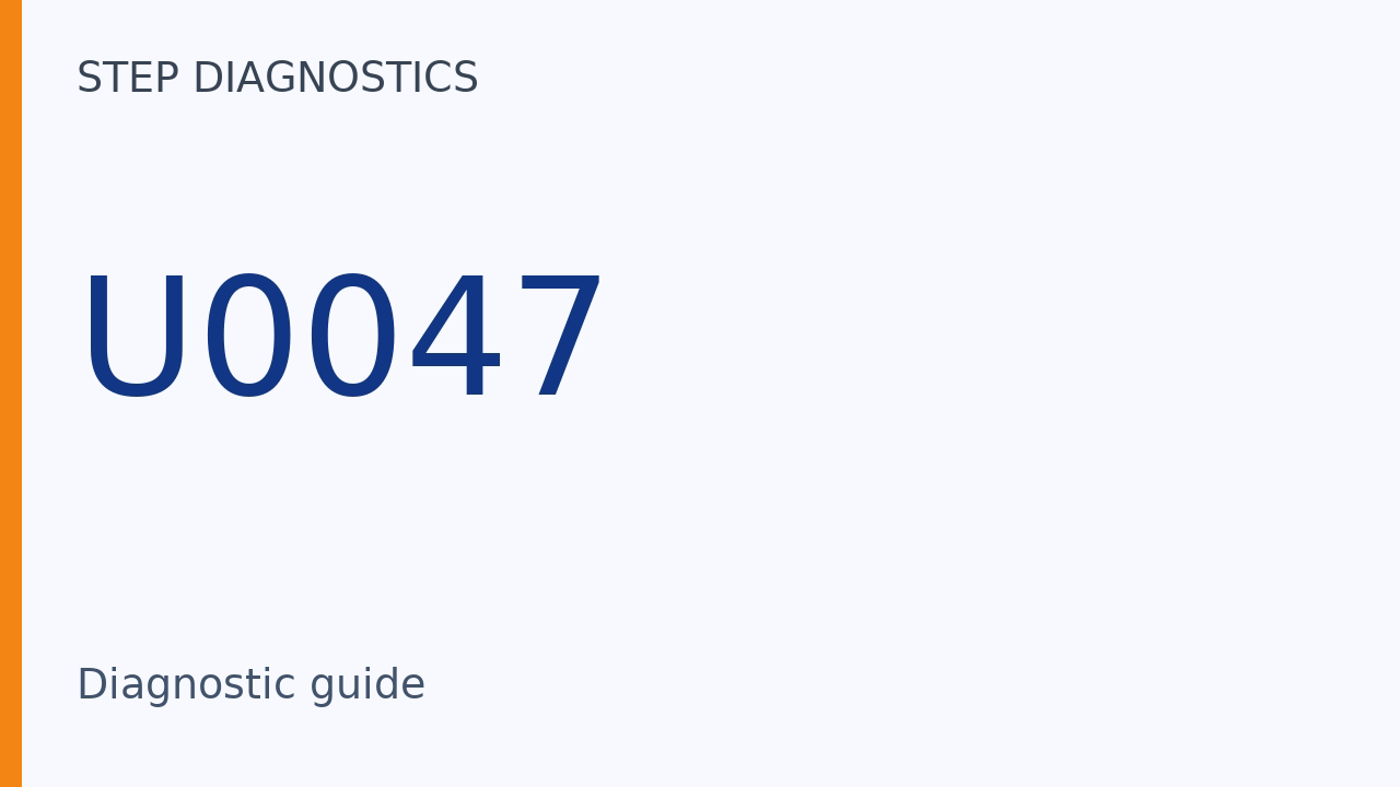
What this code means
U0047 can indicate that the CAN gateway cannot receive signals via PD-CAN B.
What the vehicle may do
- The CAN gateway may be unable to receive signals via PD-CAN B.
- The CAN gateway can store U0047 when those signals are missing.
Possible fault areas
- Possible fault areas include the external PD-CAN B circuit.
- A connected unit or the CAN gateway may also be involved.
Diagnostic path
What U0047 means
On this 2025 Honda Accord 1.5, U0047 means CAN Gateway F-CAN ch B Bus Off. The CAN gateway stores this code when it cannot receive signals via PD-CAN B. Possible fault areas include the external circuit, a connected unit, and the CAN gateway itself. Here is what this code tells us. The CAN gateway may be unable to receive signals via PD-CAN B. The CAN gateway can store U0047 when those signals are missing. Here are the main areas to check. Possible fault areas include the external PD-CAN B circuit. A connected unit or the CAN gateway may also be involved.
Shared resistance method: body ground
First, here is the shared resistance-check method used for short-circuit checks. Use the specific inspection points and measurement conditions given for the circuit being checked. In this method, disconnect the connector on each component that is part of that circuit. Measure resistance between the connector terminal being checked and body ground. The normal reading is more than 1 MΩ, with no continuity.
Shared resistance method: other ground lines
The next measurement in that shared method is to other GND lines within the same connector. Measure resistance between the terminal being checked and those ground lines. The normal reading is more than 1 MΩ, with no continuity.
These measurements use the same normal limit but check different connections: the inspected terminal to body ground, and that terminal to other GND lines within the same connector. A reading of more than 1 MΩ, with no continuity, applies to the connection actually measured; it does not stand in for the other measurement.
Shared voltage method
There is also a separate voltage method for checking a short to body ground. This method can use a circuit presumed normal with either battery or reference voltage. Disconnect the connector of the component receiving that power supply or reference voltage. Place one probe on that connector's power-supply or reference-voltage terminal. Place the other probe on body ground and measure voltage. Do these voltage checks in different vehicle modes: ON, OFF, ACC, and other applicable modes. The normal reading is the power supply or reference voltage.
Before troubleshooting
Before you troubleshoot, review How to Troubleshoot.
Separate confirmation procedure
The separate confirmation procedure has one action. Turn the vehicle to the ON mode, and wait 6 seconds.
External wiring: between the two lines
The PD-CAN B_H, PD-CAN B_L Shorted Wire Inspection is a separate procedure. Before disconnecting the PCM connector, use the diagnostic scanner (HDS) to jump the SCS line. Wait more than 1 minute. This inspection requires CAN gateway connector A (24P) and PCM connector A (72P) disconnected. For the PD-CAN B_H, PF-CAN B_L wire-to-wire check, IG Mode must be OFF. At the disconnected CAN gateway connector A (24P) female terminals, place one probe on terminal 23 and the other on terminal 11. Measure resistance. The normal reading is more than 1 megaohm.
External wiring: terminal 23 to ground
For the following short-circuit checks, use the shared inspection methods explained earlier, according to the circumstances. For the PD-CAN B_H ground-short check, IG Mode must be OFF and CAN gateway connector A (24P) must be disconnected. Place one probe on female terminal 23 of that connector and the other on ground. Measure resistance. The normal reading is more than 1 megaohm.
External wiring: terminal 11 to ground
For the PD-CAN B_L ground-short check, IG Mode must be OFF and CAN gateway connector A (24P) must be disconnected. Place one probe on female terminal 11 of that connector and the other on ground. Measure resistance. The normal reading is more than 1 megaohm. If an external-wiring inspection gives an abnormal result, there is a problem in the circuit.
The between-lines check and the two ground checks cover different short-circuit paths. Measuring terminal 23 to terminal 11 checks the connection between the lines; measuring each terminal to ground checks each line separately against ground. This is why a normal between-lines result does not settle either ground check. An abnormal external-wiring result points to a circuit problem.
Connected unit: between the two lines
The PD-CAN B Bus Connected Unit Check is a separate procedure. Before disconnecting the PCM connector, jump the SCS line with the scanner. Wait more than 1 minute. This check can be done before the other inspections are completed because it includes those inspection items. However, if it fails, each inspection item must be checked individually to find which one failed. The stated precondition is that the external circuit is normal. The preparation requires CAN gateway connector A (24P) and PCM connector A (72P) disconnected. Reconnect the listed connector, PCM connector A (72P), and make the following checks. For the internal-short check between the lines, IG Mode must be OFF. CAN gateway connector A (24P) must remain disconnected. At its female terminals, check between terminal 23 and terminal 11. The normal result is not shorted. If the result is abnormal, the unit whose connector was connected has a shorted circuit.
The important difference from the external-wiring check is that PCM connector A (72P) is reconnected while CAN gateway connector A (24P) remains disconnected. With IG Mode OFF, the between-lines measurement therefore belongs to the connected-unit inspection, not the earlier disconnected external-circuit inspection. The conclusion that the connected unit has a shorted circuit depends on the stated precondition that the external circuit is normal.
The permission to run this procedure early does not remove that diagnostic distinction. Because the procedure includes the other inspection items, an early failure still requires individual inspections to establish which item failed; the combined failure alone does not isolate the unit.
Connected unit: terminal 23 to ground
For the next internal-short check, IG Mode must be OFF. CAN gateway connector A (24P) must be disconnected. At its female terminals, check terminal 23 to ground. The normal result is not shorted. If the result is abnormal, the unit whose connector was connected has a shorted circuit.
Connected unit: terminal 11 to ground
For the final internal-short check, IG Mode must be OFF. CAN gateway connector A (24P) must be disconnected. At its female terminals, check terminal 11 to ground. The normal result is not shorted. If the result is abnormal, the unit whose connector was connected has a shorted circuit.
Conditional gateway conclusion
If all the other inspection items check out normal, the remaining CAN gateway is determined to be the cause.
The gateway conclusion is reached by the other inspections checking normal, not by the stored code alone. The code records the gateway's inability to receive signals via PD-CAN B; the normal results from the other inspection items are what make the gateway the remaining cause.
Final check
The checks can identify an external circuit problem, a connected-unit short, or the CAN gateway as the remaining cause.
For more guided automotive diagnostics, visit STEP Diagnostics.