What this code means
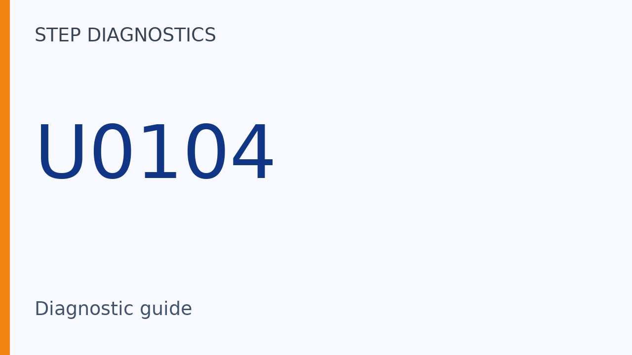
U0104 can indicate that the gauge control module is not receiving specified data from the millimeter wave radar.
The code identifies missing data at the gauge control module, not a confirmed failure of the radar itself. A radar that does not start normally or has a power/ground circuit fault can also lead to this code. That is why the radar power/ground check comes before the communication troubleshooting.
What the vehicle may do
- The gauge control module may not receive specified radar data.
- The code may be stored when the radar does not start normally.
Possible fault areas
- Possible fault areas include the radar power/ground circuit.
- The AF-CAN A_H or AF-CAN A_L circuit may have an open wire.
- The millimeter wave radar itself may have a problem.
Diagnostic path
What U0104 means
On this 2025 Honda Accord 1.5, U0104 means Gauge Control Module Lost Communication With Driving Support System Control Unit. If the gauge control module cannot receive the specified data from the millimeter wave radar, it recognizes a fault and stores U0104. Here is what this code tells us. The gauge control module may not receive specified radar data. The code may be stored when the radar does not start normally. Here are the main areas to check. Possible fault areas include the radar power/ground circuit. The AF-CAN A_H or AF-CAN A_L circuit may have an open wire. The millimeter wave radar itself may have a problem.
U0104 prerequisites
Before you troubleshoot U0104, review How to Troubleshoot. If you are troubleshooting multiple DTCs, follow B-CAN System Diagnosis Test Mode A.
Check radar power and ground first
A failure in the millimeter wave radar power/ground circuit may cause this code to be stored. Before you begin this troubleshooting, check the radar power/ground circuit first.
The communication troubleshooting path
For U0104, follow the troubleshooting for F-CAN Lost Communication (CAN BUS with Connection to CAN Gateway).
Before the shared communication checks
These shared checks cover lost communication on the F-CAN circuit connected to the CAN gateway. Before you troubleshoot, review How to Troubleshoot. If the failure is intermittent or difficult to reproduce, review How to Troubleshoot (Handling Intermittent and Low Reproducibility Failures). We will use the diagnostic scanner (HDS). For details on its Communication Status Check of F-CAN Connected Units, review How to Troubleshoot (Handling Ongoing Failures).
Check the transmitting unit
If a transmitting control unit shows NG in Communication Status Check of F-CAN Connected Units, check that unit's power/ground circuit.
Other network faults come first
Troubleshoot any DTCs listed or indicated systems below first. - Network Communications \[CAN gateway\]: Go to the indicated DTC's troubleshooting
If DTCs are present for Network Communications \[CAN gateway\], troubleshoot those indicated DTCs first.
Check communication status
Use the scanner to run Communication Status Check of F-CAN Connected Units. Then carry out the applicable checks for the control unit that shows NG.
Shared confirmation routine
The shared Confirmation Procedure is a separately defined routine. Its action is to turn the vehicle to the ON mode. For details, check the Confirmation Procedure for U0104.
When the radar shows NG
The listed scanner function path is CAN Gateway > Function Test > Communication Status Check of F-CAN Connected Units. The physical wire checks that follow are a separate test. Carry them out if Millimeter Wave Radar shows NG in Communication Status Check of F-CAN Connected Units.
A Millimeter Wave Radar NG result selects the radar wiring inspection; it does not by itself distinguish a circuit problem from a radar problem. The separate AF-CAN A_H and AF-CAN A_L open-wire checks provide that distinction.
Check AF-CAN A_H
For these wire checks, IG Mode must be OFF. CAN gateway connector B (24P) and Millimeter wave radar connector (8P) must both be disconnected. To check AF-CAN A_H for an open wire, measure resistance between these terminals. Place one probe on CAN gateway connector B (24P) female terminal 14. Place the other probe on Millimeter wave radar connector (8P) female terminal 2. The normal reading is less than 1 ohm.
Check AF-CAN A_L
For the AF-CAN A_L open wire check, IG Mode must be OFF. CAN gateway connector B (24P) and Millimeter wave radar connector (8P) must both be disconnected. Measure resistance between these terminals. Place one probe on CAN gateway connector B (24P) female terminal 2. Place the other probe on Millimeter wave radar connector (8P) female terminal 3. The normal reading is less than 1 ohm.
What the wire checks mean
If the wire checks are abnormal, there is a problem in the circuit. If the wiring checks out, there is a problem with the millimeter wave radar.
Within this radar-NG path, after the required power/ground check, the normal-wiring conclusion depends on both open-wire checks, not just one. Each must read less than 1 ohm with IG Mode OFF and both specified connectors disconnected; exactly 1 ohm does not meet that limit. An abnormal result points to the circuit, while normal results for both checks lead to the stated radar diagnosis.
U0104 confirmation routine
The U0104 Confirmation Procedure is a separate routine. Its action is to turn the vehicle to the ON mode.
Listed scanner function
Another listed scanner function path is Body Electrical > Gauges > Data List.
More diagnostic steps
For more diagnostic steps, visit stepdiagnostics.com.
Final check
Possible fault areas include radar power and ground, the communication wiring, and the millimeter wave radar.
For more guided automotive diagnostics, visit STEP Diagnostics.