What this code means
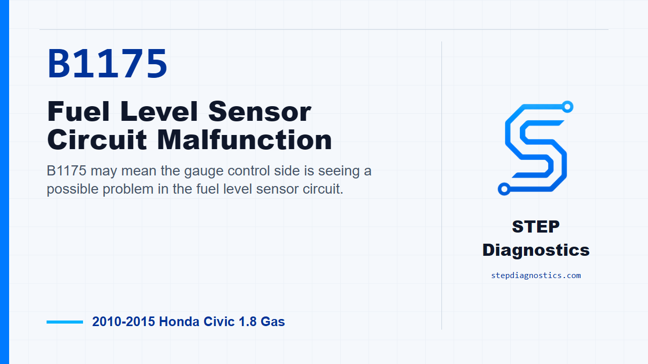
B1175 may mean the gauge control side is seeing a possible problem in the fuel level sensor circuit.
What the vehicle may do
- The fuel gauge may move to empty.
- The low fuel indicator may blink.
- Fuel level information may be unreliable.
Possible fault areas
- Fuel gauge sending unit
- Fuel level sensor circuit wiring or connections
- Gauge control module
Diagnostic path
Opening context
On this 2010 to 2015 Honda Civic with the 1.8 gas engine, B1175 points to a possible fuel level sensor circuit problem. In plain language, the gauge control side may not be seeing the fuel sender circuit the way it expects. The driver may notice the fuel gauge acting wrong, moving toward empty, or the low fuel indicator blinking. The broad fault areas can include the fuel gauge sending unit, the sender wiring and connections, or the gauge control module. For this code, the diagnostic logic is simple: first confirm what the gauge is doing, then simulate the sender, then split the circuit into the positive and negative side checks.
Confirm the gauge behavior
Start by checking the fuel gauge. If the gauge moves to the empty position and the low fuel indicator blinks, continue into the circuit test. If it does not do that, treat it as an intermittent failure for now. The system is OK at this time, so focus on loose or poor connections before going any deeper.
Simulate the fuel sender and watch for full sweep
Next, check fuel gauge operation by simulating the sending unit. Turn the ignition switch to LOCK (0), then disconnect the fuel gauge sending unit 4P connector. Connect terminal A to terminal B using a 2 Ω resistor and a jumper wire. Terminal A is the fuel gauge sending unit 4P connector No. 2, the PUR wire, and terminal B is body ground. Then remove the No. A29 (10 A) fuse from the under-hood fuse and relay box for at least 10 seconds, reinstall it, turn the ignition switch to ON (II), and check the fuel gauge. If the gauge moves to the full position, the gauge can respond to the simulated sender input, so move to the FUEL_GAGE- side continuity check. If the gauge does not move to full, go to the FUEL_GAGE+ voltage check.
Check the FUEL_GAGE+ side when the gauge does not go full
If the simulated sender test did not drive the gauge to full, check the FUEL_GAGE+ line. Keep the fuel gauge sending unit 4P connector disconnected, turn the ignition to ON (II), and measure voltage between the gauge control module, tach 32P connector No. 22, the PUR wire, and body ground. If there is battery voltage, repair an open or high resistance in the wire. If there is not battery voltage, replace the gauge control module, tach.
Check the FUEL_GAGE- side when the gauge does go full
If the simulated sender test did drive the gauge to full, move to the FUEL_GAGE- line. Turn the ignition switch back to LOCK (0), disconnect the gauge control module, tach 32P connector, and check continuity between the gauge control module 32P connector No. 21, the LT BLU wire, and the fuel gauge sending unit 4P connector No. 4, the ORN wire. If there is continuity, replace the fuel gauge sending unit. If there is no continuity, repair an open or high resistance in the wire.
Closing takeaway
The takeaway on B1175 is to let the gauge response guide the path. Confirm the empty-and-blinking symptom, use the resistor test to prove whether the gauge can sweep full, then test the side of the sender circuit that matches the result. For more diagnostic training, visit stepdiagnostics.com.
Final check
This diagnosis often depends on simulating the sender first, then using the gauge response to choose the correct circuit check.
For more guided automotive diagnostics, visit STEP Diagnostics.