What this code means
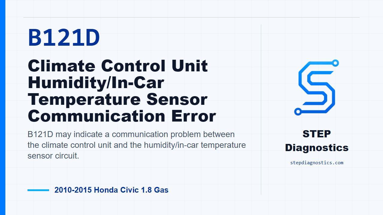
B121D may indicate a communication problem between the climate control unit and the humidity/in-car temperature sensor circuit.
What the vehicle may do
- Automatic climate control may respond incorrectly.
- The system may store the code during a climate control self-diagnostic.
- Cabin temperature or humidity input can be unreliable when the circuit is not communicating correctly.
Possible fault areas
- Possible wiring opens or shorts between the climate control unit and the humidity/in-car temperature sensor.
- Possible sensor circuit supply or communication line issue.
- Possible humidity/in-car temperature sensor issue.
- Possible climate control unit issue.
Diagnostic path
Opening context
On this 2010 to 2015 Honda Civic with the 1.8 gas engine, B121D may point to a communication problem in the climate control system, specifically around the humidity and in-car temperature sensor circuit. The customer may notice the automatic climate control responding incorrectly, or the system may simply store the code during self-diagnosis. The broad areas in play can be the sensor, the climate control unit, and the wiring between them, including the supply, communication, and possible short-to-ground paths. Start by proving the fault is active before chasing the circuit.
Verify the fault first
Clear the code with the HDS. Then turn the ignition switch to LOCK (0), turn it back to ON (II), run the self-diagnostic with the HDS or the climate control unit, and check for codes again. If B121D is still indicated, continue into the circuit checks. If it is not indicated, treat it as an intermittent failure and do not force a hard-part conclusion from a fault that is not present right now.
Check the sensor 5 volt supply
With the fault verified, turn the ignition switch to LOCK (0), disconnect the humidity/in-car temperature sensor 4P connector, then turn the ignition switch to ON (II). Measure the S_5V circuit between humidity/in-car temperature sensor 4P connector No. 1, the BLK wire, and body ground. The expected result is about 5 V. If about 5 V is present, move on to the SENSOR_COM line. If it is not present, move to the S_5V open-wire check.
Check SENSOR_COM for an open
Turn the ignition switch back to LOCK (0). Disconnect the climate control unit 32P connector, with the humidity/in-car temperature sensor still disconnected. Check continuity on the SENSOR_COM circuit between climate control unit 32P connector No. 20, the RED wire, and humidity/in-car temperature sensor 4P connector No. 3, also the RED wire. If there is continuity, that wire is okay and you can continue. If there is no continuity, repair the open between the climate control unit and the humidity/in-car temperature sensor.
Check the HUM_DATA and TR path together
Next, leave the ignition in LOCK (0), keep both connectors disconnected, and jumper the humidity/in-car temperature sensor 4P connector terminals No. 2, the YEL wire, and No. 4, the LT BLU wire. Now check continuity at the climate control unit connector between 32P connector No. 22, the YEL wire, and No. 23, the LT BLU wire. If there is continuity, continue to the short-to-ground checks. If there is no continuity, go to the open-wire check for the HUM_DATA side of the circuit.
Separate short-to-ground direction on HUM_DATA and TR
With the jumper still in place from the previous check, check continuity from climate control unit 32P connector No. 22, the YEL wire, to body ground. If there is continuity, disconnect the jumper and check that same YEL wire to body ground again. If continuity remains after the jumper is removed, repair a short to body ground in the YEL wire between the climate control unit and the humidity/in-car temperature sensor. If continuity goes away after removing the jumper, repair a short to body ground in the LT BLU wire between those same two components. If the first ground check did not show continuity, continue to the short-between-wires check later in the path.
If the 5 volt supply was missing
If the earlier S_5V check failed, turn the ignition switch to LOCK (0), disconnect the climate control unit 32P connector, and check continuity on the S_5V circuit between climate control unit 32P connector No. 16, the BLK wire, and humidity/in-car temperature sensor 4P connector No. 1, also the BLK wire. If there is continuity, repair a short in the wires between the climate control unit and the humidity/in-car temperature sensor. If there is no continuity, repair the open in the wire between the climate control unit and the humidity/in-car temperature sensor.
If the HUM_DATA and TR jumper path was open
If the jumper path between the HUM_DATA and TR circuits did not show continuity, disconnect the jumper. Then check continuity on the HUM_DATA line between climate control unit 32P connector No. 22, the YEL wire, and humidity/in-car temperature sensor 4P connector No. 2, the YEL wire. If there is continuity, repair an open in the LT BLU wire between the climate control unit and the humidity/in-car temperature sensor. If there is no continuity, repair an open in the YEL wire between those components.
Check for a short between HUM_DATA and TR
If the earlier ground check did not point to a grounded wire, disconnect the jumper and check continuity between climate control unit 32P connector No. 22, the YEL wire, and No. 23, the LT BLU wire. If there is continuity, repair a short in the wires between the climate control unit and the humidity/in-car temperature sensor. If there is no continuity, the path moves to a control-unit response check.
Final control-unit response check
For the final check, reconnect the climate control unit 32P connector. At the humidity/in-car temperature sensor 4P connector, jumper terminal No. 2, the YEL wire, to terminal No. 4, the LT BLU wire. Turn the ignition switch to ON (II), then press and hold the AUTO and ON/OFF buttons. If the mode indicator turns on, replace the humidity/in-car temperature sensor. If the mode indicator does not turn on, replace the climate control unit.
Takeaway and CTA
The clean way through B121D is to verify the code first, prove the sensor supply and communication wiring in order, and only make the sensor or climate control unit call after the circuit checks pass. For more diagnostic training, visit stepdiagnostics.com.
Final check
B121D is often best handled by proving the circuit path before making a sensor or control-unit decision.
For more guided automotive diagnostics, visit STEP Diagnostics.