What this code means
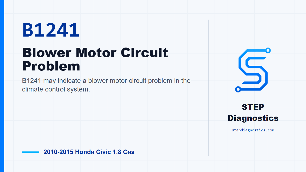
B1241 may indicate a blower motor circuit problem in the climate control system.
What the vehicle may do
- The cabin blower may not run.
- The blower may operate intermittently.
- Blower speed control may behave incorrectly.
Possible fault areas
- Possible fuse, relay, power feed, ground, wiring, or connector issues may be involved.
- The blower motor, power transistor, or climate control unit may be part of the fault area.
Diagnostic path
Code overview and starting point
On this 2010 to 2015 Honda Civic with the 1.8 gas engine, B1241 is a blower motor circuit problem in the climate control system. In plain terms, the climate control unit may not be seeing the blower circuit respond the way it should. The driver may have no cabin fan, an intermittent blower, or blower speed problems. The broad possible areas can include the blower motor power feed, fuses, relay, ground side of the circuit, the power transistor, the climate control unit, and the wiring or connectors between them. Start by clearing the DTC with the HDS. Turn the ignition switch to LOCK (0), then back to ON (II). Run the self-check with the HDS or the climate control unit and check for codes again. If the blower motor circuit code comes right back, continue into the circuit checks. If it does not return, treat it as an intermittent fault and check for loose wires or poor connections in the blower motor circuit.
Fuse checks before circuit testing
Next, turn the ignition switch back to LOCK (0) and check the blower circuit fuses. Check fuse No. A2-8, which is 40 A, in the under-hood fuse/relay box, and fuse No. B22, which is 7.5 A, in the under-dash fuse/relay box. If both fuses are good, move on to the blower motor power feed check. If either fuse is blown, replace the fuse and recheck the system. If a fuse blows again, do not keep feeding it fuses; check for a short in the No. A2-8 (40 A) fuse circuit or the No. B22 (7.5 A) fuse circuit.
Check power at the blower motor
Now check whether the blower motor is getting power. Disconnect the blower motor 2P connector, turn the ignition switch to ON (II), and measure voltage between blower motor 2P connector No. 2, the white wire, and body ground. This is the BLW_RLY output side of the circuit. If you have battery voltage there, the power feed to the motor is present and the next question is whether the motor will run. If you do not have battery voltage there, skip ahead to the relay and feed-side checks.
Command the blower motor directly
With power confirmed at the blower motor connector, turn the ignition switch to LOCK (0), reconnect the blower 2P connector, and use a jumper wire from blower motor 2P connector No. 1, the green wire, to body ground. Then turn the ignition switch to ON (II). If the blower motor runs, the motor itself can operate and you continue into the ground, power transistor, and control-side wiring checks. If the blower motor does not run during this jumper test, replace the blower motor.
Check the power transistor ground path
Turn the ignition switch to LOCK (0), remove the jumper wire, and disconnect the power transistor 4P connector. Now check continuity from the power transistor ground terminal to body ground. On a 4-door, check power transistor 4P connector No. 3, the black wire, to body ground. On a 2-door, check power transistor 4P connector No. 1, the black wire, to body ground. If continuity is present, the ground wire is okay and you keep going. If continuity is not present, repair the open between the power transistor and body ground. If the wire checks okay, check for a poor ground at G401.
Check the motor control path through the power transistor connector
Next, check the BLW-M line. Install the jumper at the power transistor connector. On a 4-door, jump power transistor 4P connector No. 3, the black wire, to No. 4, the green wire. On a 2-door, jump power transistor 4P connector No. 1, the black wire, to No. 3, the green wire. Turn the ignition switch to ON (II). If the blower motor runs at high speed, the BLW-M wire is okay and you move to the climate control signal wiring. If it does not run at high speed, repair the open between the power transistor and the blower motor.
Check the climate control signal wires for shorts to ground
Turn the ignition switch to LOCK (0), remove the jumper wire, and disconnect the climate control unit 32P connector. With both the climate control unit 32P connector and the power transistor 4P connector disconnected, check the BLOWER_G and BLOWER_V circuits for continuity to body ground one at a time. Check climate control unit 32P connector No. 12, the yellow wire, to body ground, and connector No. 13, the blue wire, to body ground. If either circuit shows continuity to ground, repair the short to body ground between the climate control unit and the power transistor. If there is no continuity to ground, those two signal wires are not shorted to ground, so continue to the open-circuit check.
Check the climate control signal wires for opens
Now check continuity through the BLOWER_G to BLW-G circuit and the BLOWER_V to BLW-V circuit between the climate control unit and the power transistor. On a 4-door, check climate control unit 32P connector No. 12, yellow, to power transistor 4P connector No. 1, yellow; then check climate control unit 32P connector No. 13, blue, to power transistor 4P connector No. 2, blue. On a 2-door, check climate control unit 32P connector No. 12, yellow, to power transistor 4P connector No. 2, yellow; then check climate control unit 32P connector No. 13, blue, to power transistor 4P connector No. 4, blue. If continuity is present on both circuits, the signal wiring is okay and you move to the power transistor check. If continuity is missing, repair the open between the climate control unit and the power transistor.
Test the power transistor and decide the control-side repair
Reconnect the climate control unit 32P connector and test the power transistor. If the power transistor tests okay after the wiring has passed, replace the climate control unit. If the power transistor does not test okay, replace the power transistor. One important check here: if the power transistor is faulty, inspect the blower motor for damage. If necessary, replace the blower motor.
Relay path when the blower motor has no power
If the earlier blower motor connector check did not show battery voltage on the power feed, move to the relay side of the circuit. Turn the ignition switch to LOCK (0), remove the blower motor relay from the under-hood fuse/relay box, and test the relay. If the relay tests okay, continue with the relay socket power, ignition, and ground checks. If the relay does not test okay, replace the blower motor relay.
Check relay socket battery feed
With the blower motor 2P connector disconnected and the blower motor relay removed, measure voltage between blower motor relay 5P socket No. 1 and body ground with the ignition switch at LOCK (0). This checks the +B_HTR_MTR feed. If battery voltage is present, that feed is okay and you keep going. If battery voltage is not present, the +B_HTR_MTR wire is open, and the repair path is to replace the under-hood fuse/relay box.
Check relay socket ignition feed
Next, turn the ignition switch to ON (II). Measure voltage between blower motor relay 5P socket No. 3, the brown wire, and body ground. This checks the IG2_A/C circuit with the blower motor connector disconnected and the relay removed. If battery voltage is present, the IG2_A/C wire is okay and you continue to the ground-side check. If battery voltage is not present, repair the open between the No. B22 (7.5 A) fuse in the under-dash fuse/relay box and the blower motor relay.
Check relay socket ground and final relay-side branch
Turn the ignition switch back to LOCK (0). Check continuity between blower motor relay 5P socket No. 5, the black wire, and body ground. This is the relay ground circuit check. If continuity is present, repair the open between the blower motor relay and the blower motor. If continuity is not present, repair the open between the blower motor relay and body ground. If that wire checks okay, check for a poor ground at G401.
Verification and takeaway
After any repair, clear the code, operate the system, and verify the repair by confirming the blower works correctly and the code stays gone. The key on B1241 is to split the circuit cleanly: confirm the fuses, verify motor power, prove the motor can run, then work through the power transistor, climate control signal wires, relay feed, ignition feed, and ground side without guessing. For more diagnostic training, visit stepdiagnostics.com.
Final check
This code is often best approached as a structured electrical diagnosis: verify the code, check the protected power feeds, prove the motor can run, then isolate the relay, ground, power transistor, /,
For more guided automotive diagnostics, visit STEP Diagnostics.