What this code means
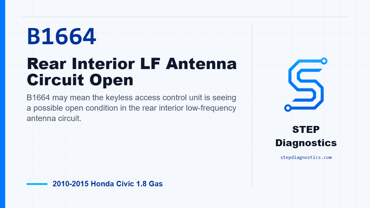
B1664 may mean the keyless access control unit is seeing a possible open condition in the rear interior low-frequency antenna circuit.
What the vehicle may do
- The vehicle may have key recognition concerns inside the cabin.
- The one-push start or keyless access operation can act intermittent.
- The code may be stored even when the system appears to work normally.
Possible fault areas
- A possible rear interior LF antenna issue.
- Possible connector fit, terminal contact, open wiring, or high resistance in the antenna circuit.
- A possible keyless access control unit issue after the antenna circuit checks good.
Diagnostic path
Code overview and setup
B1664 on this Civic points to a rear interior LF antenna circuit open in the keyless access and one-push start system. In plain language, the control unit may not be seeing the rear cabin antenna circuit the way it expects. The vehicle may have key recognition or push-start complaints, it may act intermittent, or it may only store the code. The broad fault areas are the rear interior antenna, the connector or wiring between the antenna and the keyless access control unit, and, after the circuit checks out, the control unit itself. Start by clearing the DTCs with the HDS. Then go into the keyless access control unit from the one-push start system menu, run the self check, and check whether B1664 comes back.
Confirm whether the fault is current
If B1664 is not indicated after the self check, treat it as an intermittent failure. The system is OK at that moment, so concentrate on loose terminals, poor connector fit, and connection quality instead of forcing a parts call. If B1664 is indicated, move on to the circuit output check.
Check the antenna output from the control unit
For the output check, put the vehicle in OFF mode with the engine start/stop button, then disconnect the middle interior LF antenna 2P connector. Put the vehicle back in ON mode. With the HDS, go into functional tests for keyless access control. Connect the voltmeter across the middle interior LF antenna connector: No. 1, GRN, and No. 2, LT BLU. Then command CABIN REAR ANTENNA L DC OUTPUT with the HDS and look for voltage.
Use the output result to choose the next path
If there is voltage during that commanded output test, the diagnostic path calls for replacing the middle interior LF antenna. If there is no voltage, do not condemn the antenna yet. Keep going and check the EXT_R+ and EXT_R- wires for an open or high resistance condition.
Check the EXT_R+ and EXT_R- circuits
Put the vehicle back in OFF mode. Disconnect keyless access control unit connector A, the 32P connector. With the middle interior LF antenna connector still disconnected and connector A disconnected, check continuity on both circuits. For EXT_R+, check between keyless access control unit connector A No. 31, WHT, and middle interior LF antenna connector No. 2, LT BLU. For EXT_R-, check between keyless access control unit connector A No. 15, LT GRN, and middle interior LF antenna connector No. 1, GRN.
Interpret the continuity result
If both continuity checks are good, the EXT_R+ and EXT_R- wires are considered OK, and the diagnostic path calls for replacing the keyless access control unit. If continuity is not present, repair the open or high resistance in the wire. After the repair path is completed, verify the fault the same way you started: clear the code, run the self check, and confirm B1664 stays gone. The takeaway is simple: prove the code is current, command the antenna output, then separate an antenna problem from a wiring problem before calling the control unit. For more diagnostic training, visit stepdiagnostics.com.
Final check
Confirm the code is current, command the antenna output, then use continuity testing to separate the antenna, wiring, and control unit paths.
For more guided automotive diagnostics, visit STEP Diagnostics.