What this code means
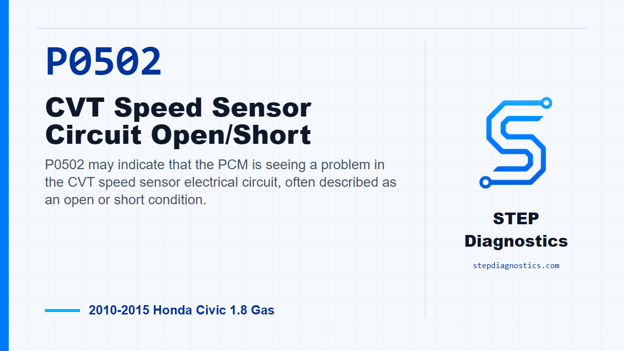
P0502 may indicate that the PCM is seeing a problem in the CVT speed sensor electrical circuit, often described as an open or short condition.
What the vehicle may do
- The vehicle may have speed-signal-related CVT behavior.
- The code may return when the operating conditions that run the monitor are repeated.
- The concern can be intermittent if the code does not return during verification.
Possible fault areas
- Possible areas include the CVT speed sensor circuit wiring.
- Possible areas include connector condition or terminal contact at the sensor or PCM side.
- Possible areas include the sensor power feed, sensor ground side, and signal wire.
- A PCM-side software or control-path concern may be considered only after the specified circuit checks support it.
Diagnostic path
Opening context
On this 2010 to 2015 Honda Civic with the 1.8 gas engine and CVT, P0502 is being handled as a CVT speed sensor circuit open or short. In plain language, the PCM may be seeing a problem in the electrical signal path for that CVT speed sensor. The vehicle may show speed-signal-related CVT behavior, and the possible fault area can be in the sensor power feed, sensor ground side, signal wire, connector area, or PCM-side control path. The key point here is that this code is an electrical circuit problem. Do not chase a mechanical failure inside the transmission for this one.
Start with safe problem verification
Before going into pinpoint testing, start with the basic system checks. Then verify the problem. Turn the ignition ON, clear the code with the HDS, and raise the vehicle on a lift. Make sure it is securely supported and that all four wheels can rotate freely. Start the engine, turn VSA off, run the vehicle in D with engine speed at 1,000 rpm or higher, then release the accelerator and do not press it again for at least 4 seconds. Slow down, stop the wheels, and check for pending or confirmed P0502 with the HDS. If P0502 comes back, the failure is duplicated and you move into circuit testing. If it does not come back, treat it as intermittent for now. The system is OK at this time, and if captured operating data is available, try to reproduce the same conditions instead of guessing.
Check the VCC2 feed at the sensor connector
Next, separate the sensor from the circuit and see what the feed line is doing. Turn the ignition OFF, disconnect the CVT speed sensor 3P connector, then turn the ignition ON. Measure voltage from CVT speed sensor connector terminal No. 1, the YEL/BLU wire, to body ground. This is the VCC2 circuit. You are looking for about 5 V. If about 5 V is there, the VCC2 feed is present and the path moves on to the SG2 check. If about 5 V is not there, check the VCC2 wire for an open between the sensor and the PCM.
If VCC2 is missing, check for an open
For the VCC2 open check, turn the ignition OFF, jump the SCS line with the HDS, and disconnect PCM connector B, the 51P connector. With the CVT speed sensor connector still disconnected, check continuity between CVT speed sensor connector No. 1, YEL/BLU, and PCM connector B No. 29, also YEL/BLU. If there is continuity, the VCC2 wire is OK. At that point, update the PCM if it does not have the latest software, or substitute a known-good PCM, then recheck. If P0502 goes away after the PCM was updated, troubleshooting is complete. If P0502 goes away with a known-good PCM substituted, replace the original PCM. If there is no continuity in the VCC2 wire, repair the open between the CVT speed sensor and the PCM.
Check the SG2 side
If the VCC2 feed was about 5 V at the sensor connector, check the SG2 side next. With the ignition ON and the CVT speed sensor connector disconnected, measure between CVT speed sensor connector No. 1, YEL/BLU, and connector No. 2, GRN/YEL. This check uses the VCC2 and SG2 circuits together, and the expected result is about 5 V. If about 5 V is present, the SG2 wire is OK and you move to the VEL_DD signal circuit. If about 5 V is not present, repair an open in the SG2 wire between the CVT speed sensor and the PCM.
Check VEL_DD for a short to ground, then for an open
Now test the VEL_DD signal wire. Turn the ignition OFF, jump the SCS line with the HDS, and disconnect PCM connector B, the 51P connector. With the CVT speed sensor connector disconnected, check continuity between CVT speed sensor connector No. 3, WHT/RED, and body ground. If there is continuity, repair a short to ground in the VEL_DD wire between the CVT speed sensor and the PCM. If there is no continuity to ground, the wire is not shorted, so check it for an open. Measure continuity between CVT speed sensor connector No. 3, WHT/RED, and PCM connector B No. 8, WHT/RED. If there is continuity, the VEL_DD wire is OK, and the next action is to replace the CVT speed sensor. If there is no continuity, repair the open in the VEL_DD wire between the CVT speed sensor and the PCM.
Takeaway and close
The clean way through P0502 on this Civic is to prove the code first, then work the circuit in order: VCC2 feed, VCC2 continuity, SG2, and finally the VEL_DD signal wire for short and open conditions. Do not skip ahead, because each answer controls the next test. For more diagnostic training, visit stepdiagnostics.com.
Final check
Follow the electrical path in order and let each voltage or continuity result decide the next move.
For more guided automotive diagnostics, visit STEP Diagnostics.