What this code means
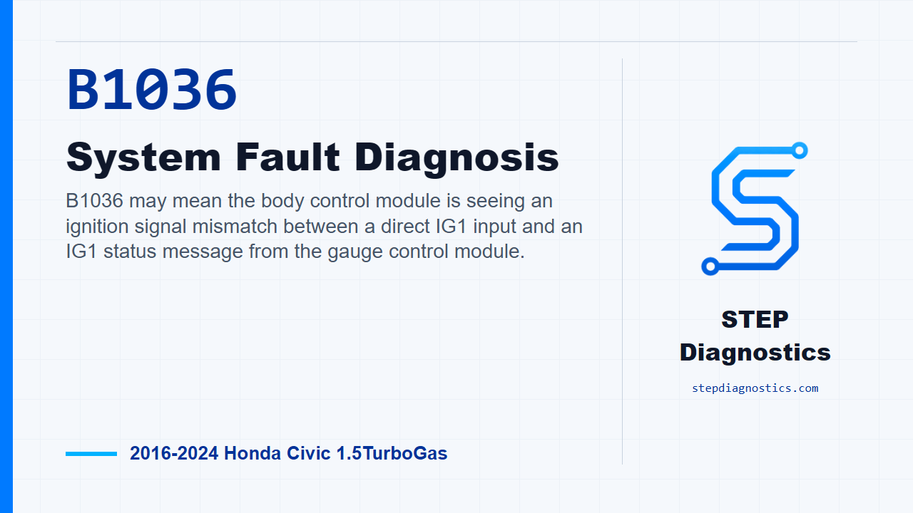
B1036 may mean the body control module is seeing an ignition signal mismatch between a direct IG1 input and an IG1 status message from the gauge control module.
What the vehicle may do
- The vehicle may have body electrical or cluster-related symptoms during ignition-on operation.
- The code can also be stored with few obvious symptoms.
Possible fault areas
- Possible IG1 feed circuit concern
- Possible connector or wiring concern
- Possible gauge control module signal path concern
- Possible body control module input-side concern
Diagnostic path
Opening context
On this Civic, B1036 is a body control module plausibility code. In plain terms, the body control module may be seeing a mismatch between the IG1 signal input and the IG1 status message coming across B-CAN from the gauge control module. The vehicle may show intermittent ignition-on related body or cluster behavior, or it may simply store the code with no obvious complaint. The broad possible fault areas can include the IG1 feed circuit, the gauge control module signal path, connector or wiring condition, and the body control module input side. The diagnostic goal is not to guess at modules. It is to prove whether the IG1 power feed being reported to the gauge control module matches what the body control module expects.
Start with the basic checks and confirm the monitor
Before isolating B1036, make sure you are using the overall troubleshooting approach for this system, not jumping straight into a parts call. If other codes are present, check what they mean first and follow the B-CAN system path before treating this as a single-code problem. To run the confirmation, turn the vehicle to the ON mode and wait for at least 6 seconds. That is the monitor gate for this code.
Understand the diagnostic logic
The logic behind B1036 is a comparison test. The body control module looks at its IG1 signal input and compares that against the IG1 signal message coming from the gauge control module over B-CAN. If those two do not agree for the required time, the body control module judges the condition abnormal and stores B1036. So the testing focuses on the external IG1 circuit feeding the gauge control module, and the exact circuit depends on whether the vehicle has auto idle stop.
Choose the correct IG1 circuit path
Use the vehicle configuration to choose the path. Without auto idle stop, inspect the IG1_METER circuit. With auto idle stop, inspect the IG1_RELAY1 circuit. Keep those paths separate, because the normal voltage check is applied to the circuit that matches the vehicle build.
Without auto idle stop: IG1_METER inspection
For a vehicle without auto idle stop, disconnect gauge control module connector A, the 32P connector. With that connector disconnected, work at the female terminals with IG Mode ON and perform the IG1_METER circuit inspection. The normal condition for that power supply check is 12 V battery voltage. If that inspection is abnormal, there is a problem in the circuit. If the power supply portion of the IG1_METER check is abnormal, continue with the additional power supply inspection to locate the failure instead of jumping straight to a module decision.
With auto idle stop: IG1_RELAY1 inspection
For a vehicle with auto idle stop, the path changes to the IG1_RELAY1 circuit. Disconnect gauge control module connector A, the 32P connector. With the connector disconnected, check at the female terminals with IG Mode ON. The normal condition for the IG1_RELAY1 power supply inspection is 12 V battery voltage. If that result is abnormal, there is a problem in the circuit. If the power supply portion of the IG1_RELAY1 check is abnormal, continue with the additional power supply inspection to locate the failure.
Verification and takeaway
Keep verification separate from the circuit test. After the circuit fault has been located through the proper inspection path, run the same confirmation conditions again: turn the vehicle to the ON mode, wait for at least 6 seconds, and confirm B1036 does not come back. The takeaway is simple: B1036 is an IG1 signal agreement problem, so prove the correct IG1 circuit for the vehicle configuration before blaming a control module. For more diagnostic training, visit stepdiagnostics.com.
Final check
This code is often approached as a signal plausibility check: prove the correct IG1 circuit path for the vehicle configuration before making any module decision.
For more guided automotive diagnostics, visit STEP Diagnostics.