What this code means
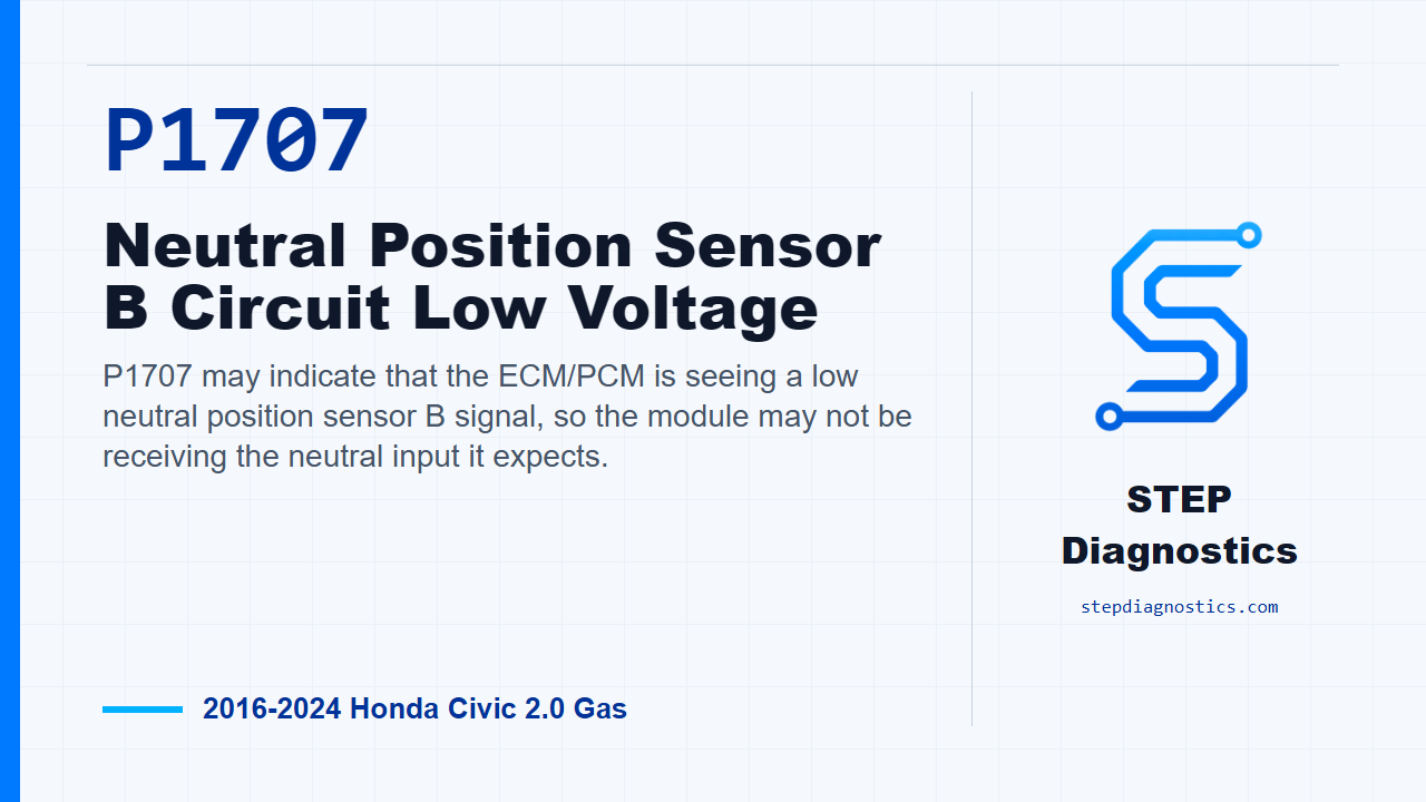
P1707 may indicate that the ECM/PCM is seeing a low neutral position sensor B signal, so the module may not be receiving the neutral input it expects.
What the vehicle may do
- The vehicle may behave normally even with the code stored.
- The vehicle can have neutral-recognition related symptoms depending on the failure.
- The concern may appear intermittently if the circuit or connector condition changes with vibration or movement.
Possible fault areas
- Neutral position sensor input area
- VCC1 and NSS2 circuit wiring or connector condition
- Possible PCM involvement after related checks are normal
Diagnostic path
Open on P1707
On this 2016 to 2024 Honda Civic with the 2.0 gas engine, P1707 means the ECM/PCM is seeing the neutral position sensor B signal lower than expected. In plain language, the module may not be getting the neutral input it expects. The vehicle may act normal, or it can have neutral-recognition related complaints depending on the failure. Broadly, think neutral position sensor, the VCC1 and NSS2 circuits, connector condition, or a possible PCM issue. Before diving into pin checks, start with the basic system checks and follow a structured diagnostic approach.
Code context before testing
First, see whether P1707 is stored by itself or stored along with the related neutral-switch circuit code. Do not get sidetracked by the code list. Use that information as context, then stay on the P1707 diagnostic path. The same main work areas apply here: inspect the neutral position sensor response, check the VCC1 and NSS2 circuits, and only consider the PCM after the earlier inspections have checked normal.
Set up the confirmation and sensor simulation
For the confirmation portion, turn the vehicle to the ON mode. Then prepare for the neutral position sensor inspection by disconnecting the neutral position sensor 4P connector. At that connector, jump terminals No. 1 and No. 4 with a jumper wire. With the jumper in place, turn the vehicle to the ON mode again and watch the HDS value for Neutral Position Sensor 2.
Interpret the HDS value
The normal HDS value for Neutral Position Sensor 2 is about 5.0 V. If that simulated input reads normal, the diagnostic path points to a problem with the neutral position sensor. If it does not read normal, move on and treat it as a problem in the related components rather than guessing at the sensor.
Check the VCC1 and NSS2 circuits
Before disconnecting the PCM connector, jump the SCS line with the HDS and wait more than 1 minute. Then disconnect the neutral position sensor 4P connector and disconnect PCM connector E, the 80P connector. Now perform the VCC1 and NSS2 circuit checks. For the OFF checks, the VCC1 open-wire inspection should show less than 1 Ω. The NSS2 open-wire inspection should also show less than 1 Ω. The NSS2 short-to-ground inspection should be not shorted. If one of these checks is abnormal, the problem is in the circuit. Use the standard open and short circuit checking method and continue based on which side failed.
PCM decision and closing takeaway
If the neutral position sensor inspection and the related circuit inspections all indicate normal, then the remaining diagnostic conclusion is a problem with the PCM. The key is to prove the sensor response and the VCC1 and NSS2 wiring first; do not jump to the PCM early. For P1707, simulate the input, verify the expected HDS response, prove the circuits, and only then make the PCM call. For more diagnostic training, visit stepdiagnostics.com.
Final check
P1707 is often approached as an electrical circuit and sensor-simulation diagnosis, where the sensor response and related wiring are checked before considering the PCM.
For more guided automotive diagnostics, visit STEP Diagnostics.