A fuel-system code can describe a mixture problem without identifying a failed fuel-system part. The engine controller sees the result of fuel delivery, measured air, combustion, exhaust flow, and sensor feedback working together. A rich-mixture complaint and a cylinder-balance complaint therefore need different evidence, even when both investigations eventually include an injector.
This overview covers the 2016-2024 Honda Civic 2.0 Gas family. The detailed operating and diagnostic examples were reviewed against a 2024 Civic Sedan with the naturally aspirated 2.0-liter engine. The year range identifies the vehicle family, not identical equipment, monitor conditions, wiring, or service procedures in every year and market. Confirm the actual engine and applicable service information before testing. Do not substitute procedures for the 1.5-liter turbo or a performance-model powertrain.
What the fuel system must accomplish
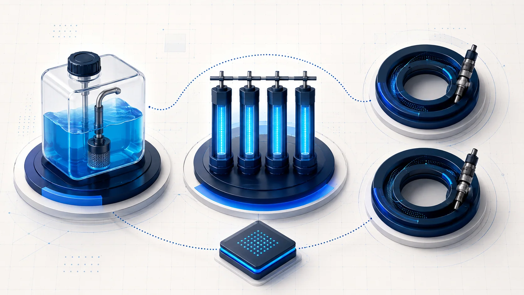
The system must supply fuel, meter the appropriate amount to each cylinder, and adjust that metering as operating conditions change. In the reviewed 2.0-liter arrangement, the fuel pump, filter, and pressure regulator are part of the tank-side supply system. The applicable pressure test distinguishes excessive pressure from insufficient pressure and includes regulator, filter, pump, and leakage possibilities. A pressure problem is not automatically a failed pump.
The PCM controls fuel quantity by changing how long an injector is energized. Injection timing is calculated with crankshaft- and camshaft-position information. These are different aspects of control: the electrical command, fuel available at the injector, and the cylinder's actual combustion result are not interchangeable measurements.
Airflow and engine speed contribute to the basic injection calculation. The controller then applies corrections, including exhaust-oxygen feedback, when the operating state permits that feedback. A reading during cold operation, starting, fuel cut, or another non-feedback condition should not be judged as though it came from a stable warmed-up feedback test.
Understand the two exhaust-feedback roles
The A/F sensor, identified as Sensor 1 in the reviewed information, gives the PCM information used to correct the air-fuel mixture. The secondary heated oxygen sensor, Sensor 2, observes exhaust after the catalyst and contributes further correction. Its role is not limited to a simple pass-or-fail label for the catalyst.
That distinction matters when reading a post-catalyst trim code. The code's name describes a monitored behavior; it is not an instruction to replace Sensor 2 or the catalytic converter. In the reviewed P2097 path, cylinder air-fuel variation and the exhaust system are investigated before the remaining Sensor 1 conclusion. Follow the diagnostic evidence rather than choosing the component closest to the words in the code title.
Fuel correction also reflects influences outside the fuel supply itself. Measured airflow, purge vapor, fuel contamination of the engine oil, fuel quality, and sensor behavior appear in the reviewed rich-mixture investigation. Treat trim information as a clue to a control problem, not a stand-alone identification of its cause.
How the four STEP guides fit together
The following guides belong to this vehicle family. Their exact test conditions and repair steps must be checked against the vehicle being repaired.
| STEP guide | Main diagnostic question | Avoid this shortcut |
|---|---|---|
| P0172 - fuel system too rich | What is driving the rich correction: supply pressure, air measurement, vapor or contamination influence, fuel quality, sensing, or injector operation? | Replacing an oxygen sensor or injector from the code alone. |
| P2097 - post-catalyst fuel trim | Have the related faults, cylinder A/F test, and exhaust leakage or restriction checks been resolved in the required order? | Assuming that a post-catalyst code proves a failed downstream sensor or catalyst. |
| P219C - cylinder air-fuel ratio variation | What explains the affected cylinder's imbalance, including mechanical condition, airflow, ignition-related context, and injector behavior? | Treating a cylinder-specific result as proof of an injector fault. |
| P219E - cylinder air-fuel ratio variation | Is the correct cylinder's data being evaluated, and does the prescribed investigation distinguish a local problem from a wider control issue? | Reusing another cylinder's data or assuming all cylinder-variation codes identify the same location. |
The reviewed shared cylinder-variation procedure associates P219C with No. 1 cylinder and P219E with No. 3. Confirm cylinder identification using the applicable service information; the physical layout should not be guessed from an illustration.
Symptoms and failure categories
A warning light may be the only obvious symptom. Rough or uneven running, hesitation, or a fuel-economy complaint can accompany a fuel-control problem, but they do not uniquely identify its cause. An intermittent concern may not be present when the vehicle first enters the workshop.
Separate the investigation into useful categories:
- Supply and regulation: test pressure with the correct equipment and conditions. Low pressure, excessive pressure, and a pump that does not operate require different diagnostic branches.
- Metering and mixture influence: an injector, purge contribution, contaminated fuel, or fuel in the engine oil can affect mixture behavior. Demonstrate the influence before choosing a repair.
- Air and exhaust evidence: inaccurate air measurement or an exhaust leak or restriction can distort the diagnosis. Sensor feedback has to be interpreted in that context.
- Cylinder-specific combustion: compression, valve clearance, intake or exhaust flow, and related ignition faults can matter when one cylinder differs from the others. Fuel delivery is only one possibility.
A practical diagnostic approach
Start by preserving pending and confirmed DTCs, freeze-frame data, and available snapshots before clearing or resetting anything. Record the complaint, the operating conditions, and relevant recent work. Check current service information and related-code priorities before treating one code in isolation.
For a rich-mixture complaint, reproduce the condition using the applicable confirmation procedure. The reviewed P0172 investigation proceeds through supply pressure, airflow, engine-oil contamination, purge influence, fuel quality, sensing, and injector checks. Some later branches use controlled known-good comparisons; they are not permission to replace a sequence of parts without a demonstrated result. PCM investigation comes after the prescribed earlier checks, not before them.
When referred to the fuel-pressure test, preserve the conditions under which the malfunction occurred. A normal measurement at a different speed or load may not settle the original complaint. Likewise, a pressure reading cannot establish that every injector or cylinder is functioning correctly.
For P2097, keep the cylinder A/F check and exhaust inspection separate. An abnormal cylinder test changes the direction of the investigation. A normal cylinder result does not eliminate a leak or restriction in the exhaust path. The source's later sensor conclusion depends on completing the preceding checks, not merely observing the code.
For P219C or P219E, address relevant sensor, injector, misfire, or ignition codes first. The reviewed procedure includes compression and valve-clearance work, manifold inspection, and an injector investigation. Use the correct cylinder data and the prescribed comparison method. Do not improvise injector swapping or mechanical adjustment from this overview; those operations require the full service procedure and correct sealing and safety practices.
Repair the demonstrated cause, then verify it
A justified repair may restore the tank-side supply, correct a wiring or connection fault identified by the applicable procedure, repair an exhaust problem, address a proven injector or sensor defect, or correct a mechanical condition affecting cylinder balance. Fuel or oil replacement should address a demonstrated contamination problem and its cause, not simply hide the symptom.
Keep fuel work controlled. Eliminate ignition sources, follow the specified pressure-relief and electrical-isolation procedure, and use suitable equipment and protective measures before opening a connection. Do not loosen a fuel fitting merely to see whether fuel is present. Check for leaks after reconnecting disturbed parts and follow the service procedure before running the engine. Running tests also require exhaust ventilation and separation from hot and moving components.
After the repair, perform only the resets or learning operations required for the actual vehicle. Then repeat the relevant functional checks and confirmation conditions. Where the procedure uses monitor status, distinguish a completed pass from a monitor that has not yet run. Check for returning and additional codes, and verify that the original complaint is resolved.
The aim is not simply to clear a warning light. It is to connect a repeatable observation to a demonstrated cause, make the appropriate repair, and confirm that the same fuel-control or cylinder-balance problem no longer occurs.