The evaporative-emissions (EVAP) system keeps gasoline vapor from venting directly to the atmosphere. On the 2010-2016 Honda CR-V 2.4 Gas, it stores vapor in a charcoal canister, meters that vapor into the engine when operating conditions permit, and gives the powertrain control module (PCM) enough feedback to check purge flow, valve control, and system sealing.
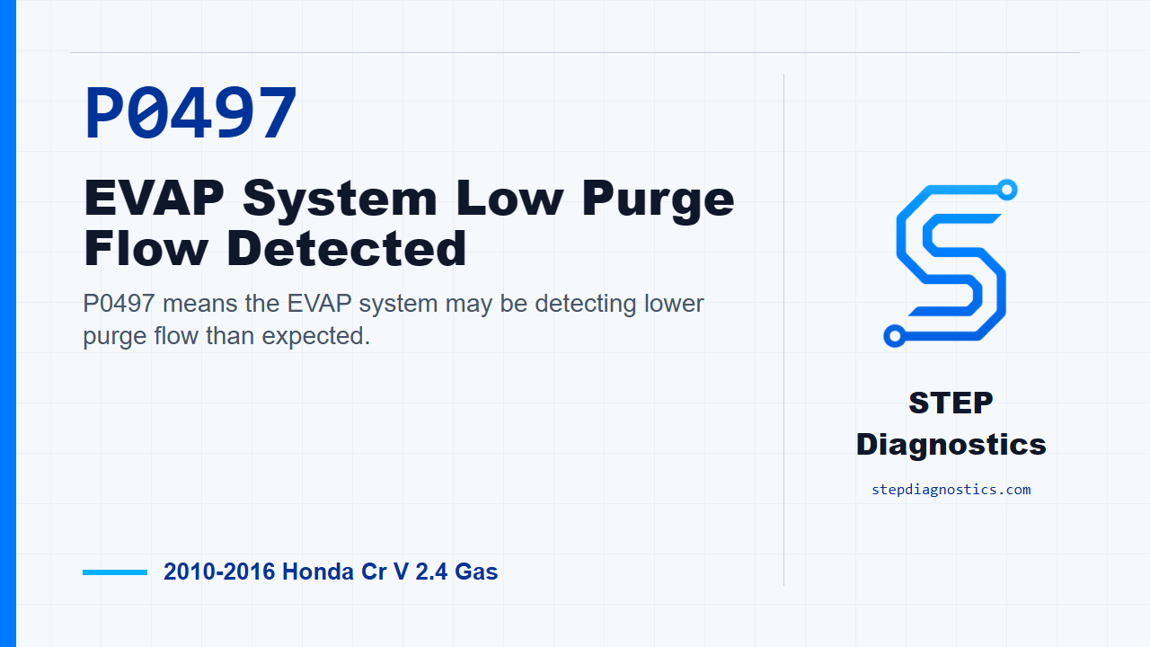
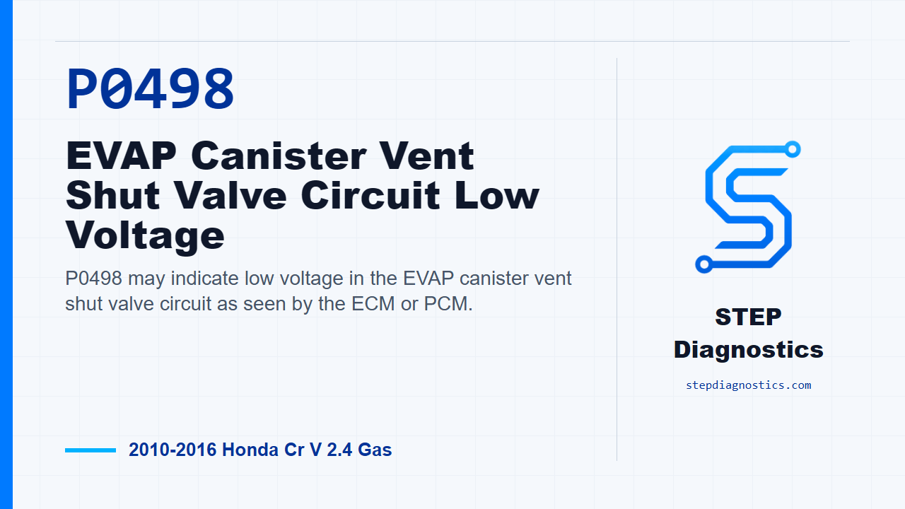
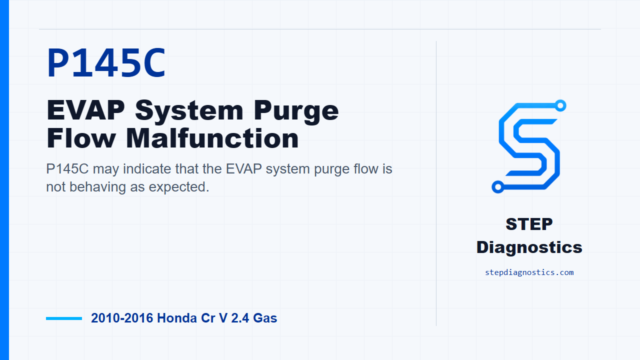
For a mechanic, the important distinction is between a flow fault and an electrical circuit fault. P0497 and P145C describe purge-flow behavior that did not match the PCM's expectation. P0498 describes low voltage in the vent shut valve control circuit. None of these codes proves that the component named in the description has failed.
Applicability and service-information boundary
This overview applies to the STEP Diagnostics vehicle profile for the 2010-2016 Honda CR-V 2.4 Gas. Source endpoints confirm a 2010 CR-V 4WD with a 2.4L engine and a 2016 CR-V 4WD with the 2.4L K24W9 engine. The detailed system description and diagnostic procedures reviewed for this overview are for the exact 2016 K24W9 target.
The principles below are educational and apply to the system as a whole. Component locations, scan-tool menus, monitor conditions, connector and terminal details, electrical values, test vacuum, time limits, and repair procedures can vary. Use the service information for the exact vehicle in the bay before performing a directed test or opening any vapor or fuel connection.
What the EVAP system does
The EVAP system has four connected jobs:
- Capture fuel vapor produced in the tank instead of releasing it to the atmosphere.
- Store the vapor in the charcoal canister while the engine is not ready to use it.
- Draw the stored vapor through the purge path and into the intake so it can be burned.
- Let the PCM evaluate purge flow and system pressure response through controlled valve operation and fuel-tank-pressure (FTP) feedback.
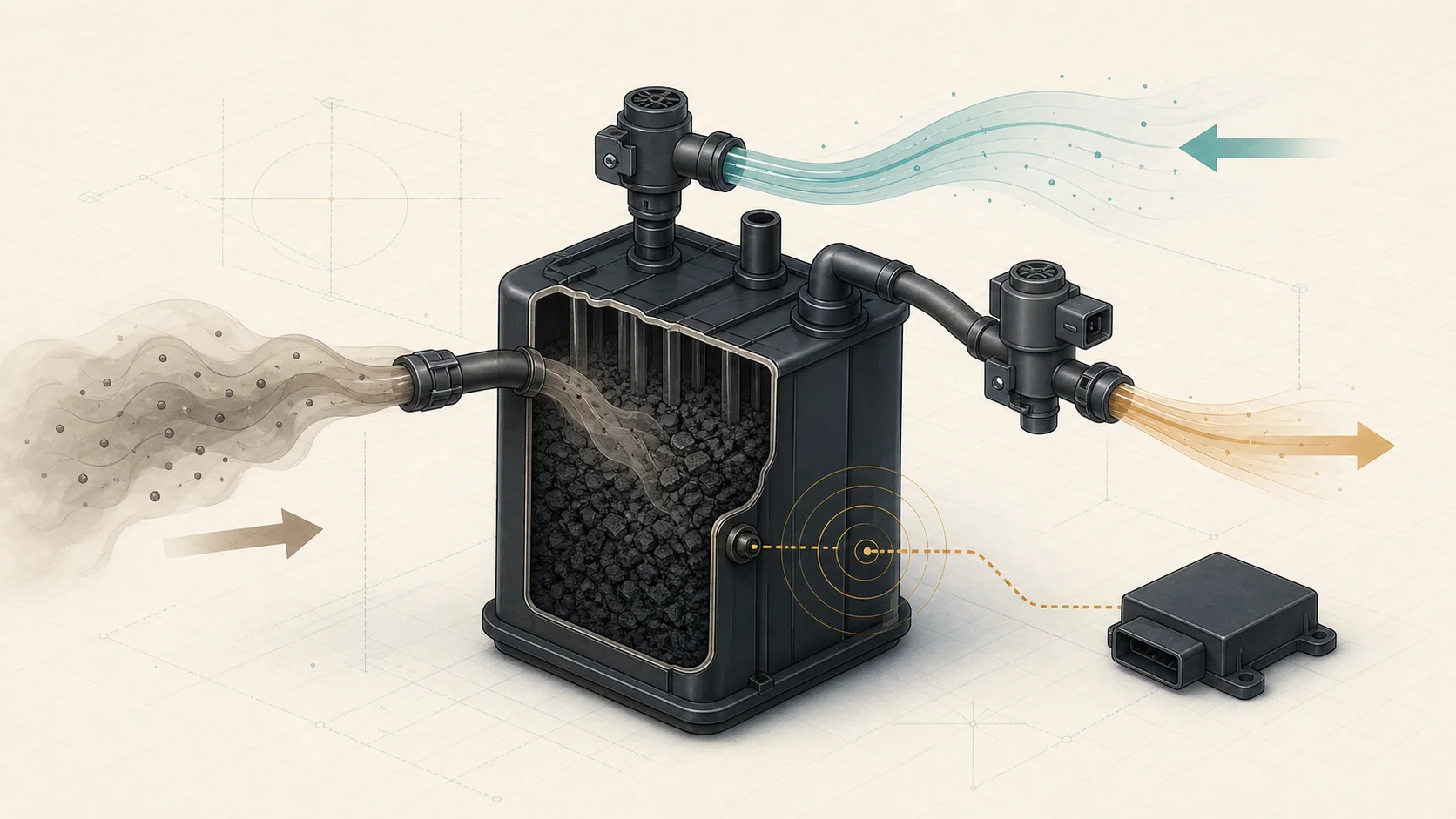
The system is easiest to understand as a controlled air-and-vapor path. Tank vapor enters the canister. The canister holds hydrocarbons while allowing the system to breathe through its vent path. When purge is permitted, intake vacuum draws fresh air through the canister and carries stored vapor toward the engine. The PCM varies the purge valve opening to regulate that flow.
During certain self-checks, the PCM changes vent and purge commands and observes the FTP sensor response. The response helps it judge whether the system behaved as expected. A wrong response can come from a valve, a hose, a restriction, a leak, an electrical circuit, a sensor, or the conditions under which the test ran.
Main functional areas
| Functional area | Normal contribution | What a mechanic should prove |
|---|---|---|
| Fuel tank and vapor lines | Contain fuel vapor and route it to the canister | Lines are correctly connected, undamaged, and free of an obvious blockage or restriction |
| Charcoal canister | Stores vapor until the engine can purge it | Air and vapor can move through the intended ports and the canister path is not damaged or restricted |
| Purge valve and purge line | Meter stored vapor from the canister into the intake | The valve receives the correct command, seals and flows when expected, and the complete purge path is open |
| Vent shut valve and fresh-air path | Let the canister breathe normally and close the system for a controlled test | The fresh-air path is open, the valve can move, and its power and control circuit are intact |
| FTP sensor and PCM monitoring | Report pressure or vacuum change while the PCM commands a test | The signal is plausible, changes in the correct direction, and agrees with known valve and plumbing behavior |
How the related DTCs differ
| DTC | Failed behavior | First diagnostic direction |
|---|---|---|
| P0497 | The system detected less purge flow than expected | Inspect the purge plumbing, then use commanded operation and pressure/vacuum response to separate a restriction, valve problem, vent problem, or FTP feedback problem |
| P0498 | The vent shut valve circuit was electrically low | Confirm the fault and prove valve power, the valve, the control wire, and connector condition before considering module control |
| P145C | Purge-flow behavior did not match the expected state | Preserve captured data, check companion EVAP codes, and use the applicable purge-flow path rather than making a stand-alone parts call |
P0497 and P145C overlap because both concern purge behavior, but their code context matters. P145C may route diagnosis through a related purge-flow code and the conditions captured when the fault set. P0498 belongs to a different category: it should begin as an electrical circuit diagnosis even though the valve also affects pneumatic system behavior.
Common symptoms
Many EVAP faults cause little or no drivability complaint. Common observations include:
- A malfunction indicator lamp with otherwise normal operation.
- An EVAP monitor that will not complete normally while the fault is present.
- An intermittent fault that may require the recorded freeze-frame or snapshot conditions to reproduce.
- Fuel or vapor odor when the system has an active leak. Treat that condition as a safety issue.
Common failure categories
Plumbing and sealing faults
Loose or damaged connections, damaged hoses, a blocked line, or a restricted port can change flow and pressure response. A visual inspection is valuable, but it must cover the entire relevant path. A hose can look acceptable while being restricted internally.
Purge-control faults
A purge valve can fail electrically, stick, leak when it should seal, or restrict flow when commanded open. The same low-flow result can also be produced by a blocked line between the valve and canister. Prove the path and the valve behavior separately.
Vent and canister faults
The vent path normally supplies fresh air through the canister. A damaged or restricted canister/vent path, a stuck vent shut valve, or a circuit fault can prevent normal breathing or prevent the system from sealing for a test. Because the vent valve has both an electrical role and an airflow role, the code family determines which side to test first.
FTP feedback faults
The PCM depends on the FTP signal to judge pressure change. An implausible signal, a sensor that does not respond, a wiring fault, or a real plumbing problem can all make the observed response wrong. Compare sensor behavior with known system commands before replacing the sensor.
Intermittent electrical faults
Canister-area connector or wiring faults can be intermittent. Inspect for poor connections, loose terminals, and visible wiring damage, then reproduce the recorded operating conditions when practical.
A system-first diagnostic strategy
1. Preserve the evidence
Record all pending and confirmed codes, freeze-frame or snapshot data, and the customer's symptom before clearing anything. Note whether other EVAP, sensor, electrical-supply, or communication codes are present. The companion-code relationship can change the correct starting point for P145C.
2. Classify the fault before testing
Decide whether the case is primarily low purge flow, purge-flow logic, an electrical vent-circuit fault, a sealing concern, or a broader sensor/supply problem. This prevents a circuit code from being chased as a plumbing fault and prevents a flow code from becoming an automatic valve replacement.
3. Perform a careful visual and safety inspection
Work in a ventilated area away from flames, sparks, hot surfaces, and other ignition sources. If fuel odor or liquid fuel is present, stop and correct the immediate hazard. Inspect accessible vapor lines, purge connections, canister and vent-path condition, connectors, and harness routing for poor connections, damage, blockage, or restriction.
Do not apply shop air or uncontrolled pressure or vacuum to the EVAP system. Excess pressure or vacuum can damage the tank, canister, valves, or FTP sensor. Use only the applicable service procedure and suitable low-pressure EVAP equipment.
4. Verify the electrical foundation
For P0498, confirm the code and begin with the circuit. Prove that the vent shut valve has the required power supply, that the valve's electrical winding is not open or shorted, and that the PCM control path has neither an open nor a short. Inspect connector and terminal condition, and reproduce the recorded operating conditions when practical.
For a flow code, still check related circuit codes first. A valve cannot create the commanded pneumatic response if its electrical control is unavailable.
5. Compare command with system response
Use the applicable scan-tool test to command purge or vent operation while observing the relevant feedback. Listen or feel for valve operation only as supporting evidence; a click does not prove sealing or flow. Compare the command with FTP response and with controlled vacuum or flow testing as directed by the exact procedure.
One result should determine the next step. If the purge path will not hold or transmit the expected vacuum, isolate the line, purge valve, canister path, vent path, and FTP response in the order given by the service information. Do not replace all components that share the same symptom.
6. Reassess after every result
After finding a blocked line, failed circuit, incorrect valve response, or abnormal FTP signal, update the case state. Decide whether that result explains every stored code and symptom. If it does not, continue with the next applicable branch rather than assuming one repair corrected unrelated evidence.
7. Verify the repair
Restore every hose, clip, connector, shield, and underbody panel disturbed during testing. Confirm there is no fuel or vapor leak. Clear codes at the correct point, repeat the applicable function test or confirmation drive, and verify that commanded valve behavior and FTP response are normal. Recheck pending as well as confirmed codes before returning the vehicle.
Repair categories
The confirmed repair may involve a damaged or restricted vapor line, a purge valve, a vent shut valve, a damaged or restricted canister/vent path, an FTP sensor or circuit, valve power or control wiring, or a connector repair. Module software or module control is considered only where the exact service procedure directs it after the applicable external checks pass.
The category is not the diagnosis. The diagnosis is the measured result that isolates the cause, followed by verification under the conditions that originally exposed the fault.
Final takeaway
Think of the CR-V EVAP system as a feedback-controlled vapor path: the canister stores vapor, the vent lets the system breathe, the purge valve meters vapor into the engine, and the FTP sensor lets the PCM judge the result. Start by preserving evidence and classifying the code. Prove electrical control for P0498; prove purge-path behavior and feedback for P0497 and P145C. Let each test result choose the next step, and use the exact service information for pressures, commands, connector details, and repair procedures.