What this code means
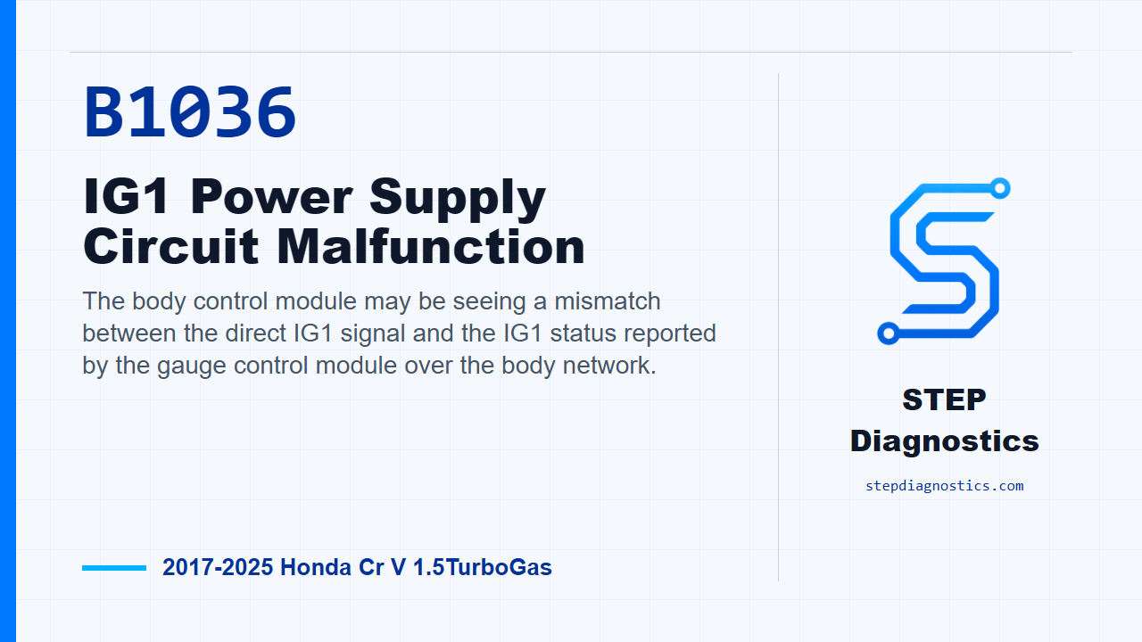
The body control module may be seeing a mismatch between the direct IG1 signal and the IG1 status reported by the gauge control module over the body network.
What the vehicle may do
- The vehicle may show body electrical or meter-related behavior.
- The code may be stored with little or no obvious symptom.
Possible fault areas
- Possible IG1 power feed circuit concern.
- Possible gauge control module connector or circuit-side concern.
- Possible mismatch between the body control module input and the body network IG1 status.
Diagnostic path
Opening context
Today we’re looking at B1036, an IG1 power supply circuit malfunction on a 2017 to 2025 Honda CR-V with the 1.5 turbo engine. In plain terms, the body control module may be seeing a mismatch between the IG1 signal it receives directly and the IG1 status being reported over the body network from the gauge control module. The vehicle may show body electrical or meter-related behavior, or it may simply store the code. The possible fault areas are the IG1 power feed circuit, the gauge control module connection area, and the signal relationship the body control module is using to make that decision.
Start clean and handle other codes first
Before getting deep into the circuit check, start with the basic system checks and follow a structured diagnostic approach. If other codes are present, do not treat B1036 in isolation. Sort out the body network diagnostic path first, then come back to this code with the system state understood.
Confirm the code under the monitor conditions
For the confirmation step, turn the vehicle to ON mode, then wait for at least 6 seconds. That gives the body control module time to compare the IG1 input against the IG1 status coming from the gauge control module. Keep the running conditions as a monitor gate; the testing comes after the code is confirmed.
Vehicle without auto idle stop
If this CR-V does not have auto idle stop, the circuit check is the IG1_METER circuit. Prepare by disconnecting gauge control module connector A, the 32P connector. With IG Mode ON, perform the inspection for that circuit. A normal result is 12 V battery voltage. If the result is abnormal, treat that as a problem in the circuit, not as an automatic module call.
Vehicle with auto idle stop
If the vehicle does have auto idle stop, use the IG1_METER(VST) circuit path instead. The preparation is the same: disconnect gauge control module connector A, the 32P connector. With IG Mode ON, inspect the IG1_METER(VST) circuit. A normal result is 12 V battery voltage. If that result is abnormal, the diagnostic direction is a circuit problem.
If the power supply check is abnormal
On either vehicle configuration, if the power supply inspection is abnormal, continue with the additional power supply inspection to locate the failure. If you reach that point and the return path is not clear, pause, recheck the earlier diagnostic path, and avoid guessing. The key is to keep the diagnosis tied to the IG1 power supply result for the correct vehicle configuration.
Verification and takeaway
After the circuit issue has been addressed, verify the repair separately from the circuit testing. Run the confirmation again: vehicle in ON mode, wait for at least 6 seconds, and confirm B1036 does not reset. The takeaway is simple: B1036 is a comparison fault around IG1 power status, so choose the correct auto-idle-stop path, check for 12 V battery voltage at the proper circuit, and let the abnormal power supply result guide the next inspection. For more diagnostic training, visit stepdiagnostics.com.
Final check
B1036 often needs a circuit-focused check of the correct IG1 meter feed path for the vehicle configuration.
For more guided automotive diagnostics, visit STEP Diagnostics.