What this code means
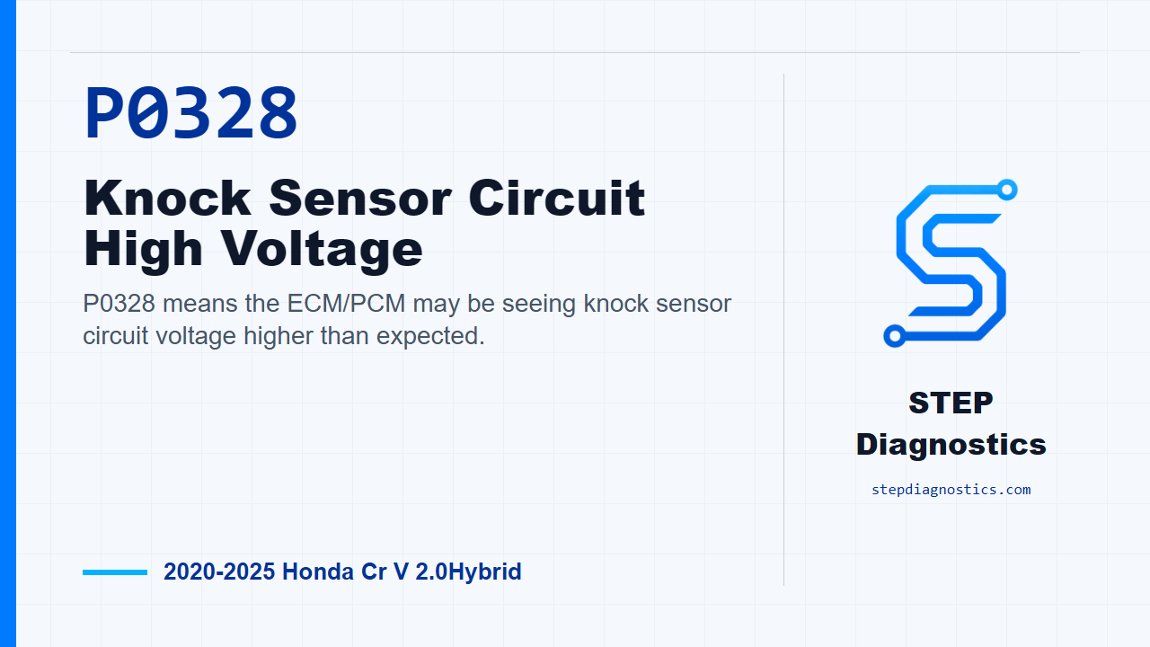
P0328 means the ECM/PCM may be seeing knock sensor circuit voltage higher than expected.
What the vehicle may do
- The vehicle may turn on a warning light.
- The vehicle can sometimes feel down on power or run with altered ignition timing strategy.
- There may be no obvious driveability complaint beyond the stored code.
Possible fault areas
- Possible fault areas can include the knock sensor circuit wiring and connectors.
- The knock sensor signal or ground path may be involved.
- The knock sensor itself may be involved.
- The PCM can be a possible fault area after the related checks are normal.
Diagnostic path
Opening and diagnostic direction
On this 2020 to 2025 Honda CR-V Hybrid, P0328 means the ECM/PCM is seeing the knock sensor circuit voltage higher than it expects. The driver may only notice a warning light, or the vehicle can sometimes feel down on power or run with altered ignition timing strategy. Broadly, this can involve the knock sensor circuit, the signal or ground wiring, the connector condition, the knock sensor itself, or, after the other checks pass, the PCM. Before getting into pinpoint testing, start with the basic system checks and follow a structured diagnostic approach. If other codes are present, understand those first so you are not chasing a symptom from another system. Also keep in mind that there is no direct component-only test here, so this diagnosis works through the related circuit checks and then uses the results to decide where the fault is pointing.
Confirm power-side behavior at the knock sensor connector
Begin the confirmation by turning the vehicle to the ON mode. Then disconnect the knock sensor connector, which is the 2P connector. With IG Mode ON, inspect the disconnected knock sensor connector female terminals. The normal unit output voltage for this check is About 5.0 V. If that inspection is normal, the diagnostic path points to a problem with the knock sensor. If it is abnormal, the path moves away from the sensor itself and toward the other related components. Make sure the exact connector terminal locations are identified before probing; if the terminal positions are unclear, pause and do not guess at the probe points.
Check the KS and KSGND circuits for opens
Next, before disconnecting the PCM connector, jump the SCS line with the HDS, and wait more than 1 minute. After that, disconnect the knock sensor connector, again the 2P connector, and disconnect PCM connector B, the 101P connector. With IG Mode OFF, inspect between the disconnected knock sensor connector female terminals and the disconnected PCM connector B female terminals. For the KS open wire inspection, the normal result is less than 1 Ω. For the KSGND open wire inspection, the normal result is also less than 1 Ω. If either result is abnormal, the problem is in the circuit. As with the earlier check, use confirmed terminal identification and avoid guessing if the connector detail is not clear.
PCM conclusion and final takeaway
If the knock sensor inspection and the KS and KSGND circuit inspections all indicate normal conditions, the remaining diagnostic conclusion is a problem with the PCM. Keep that as the end of the path, not the starting point. The takeaway is simple: for P0328, prove the knock sensor connector voltage first, then prove the KS and KSGND wiring integrity, and only after the related inspections pass should the PCM be considered the remaining cause. For more diagnostic training, visit stepdiagnostics.com.
Final check
Prove the connector voltage and circuit integrity first, then consider the remaining control-side conclusion only after those checks pass.
For more guided automotive diagnostics, visit STEP Diagnostics.