What this code means
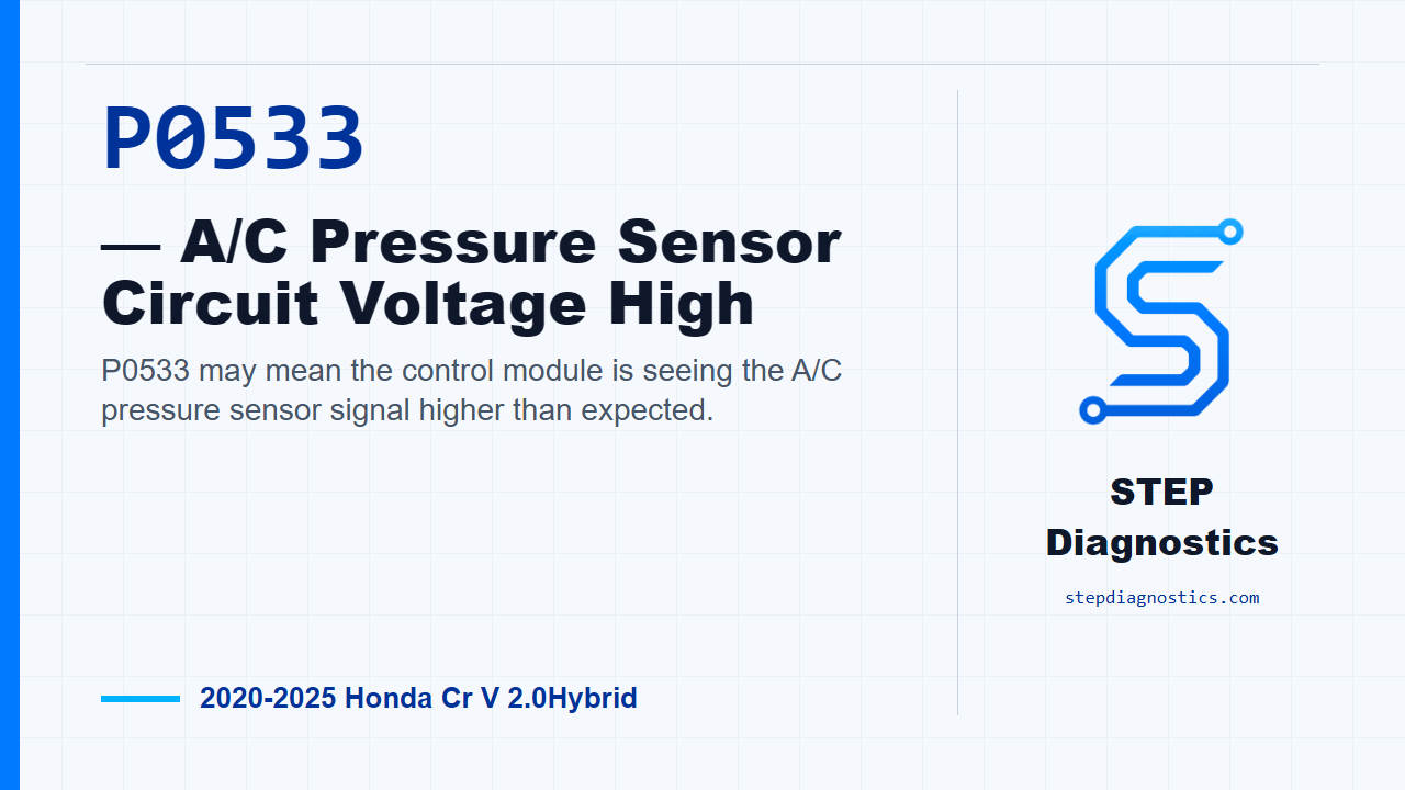
P0533 may mean the control module is seeing the A/C pressure sensor signal higher than expected.
What the vehicle may do
- The A/C may not cool normally.
- The A/C may be inhibited or limited.
- A warning light may be present even if the driver does not notice an A/C complaint.
Possible fault areas
- Possible A/C pressure sensor signal concern.
- Possible sensor ground or signal circuit concern.
- Possible connector or wiring concern between the A/C pressure sensor and the integrated control module.
- Possible integrated control module concern after related checks are normal.
Diagnostic path
Opening: what P0533 is telling us
On this 2020 to 2025 Honda CR-V Hybrid, P0533 means the integrated control module is seeing the A/C pressure sensor signal voltage higher than expected. In plain terms, the module may be interpreting the A/C pressure signal as too high. The customer may notice poor A/C operation, the A/C may be inhibited, or there may only be a warning light. Broadly, the possible fault areas can include the A/C pressure sensor signal, the sensor ground side, the connector and wiring between the sensor and the integrated control module, or the module side of the circuit. The diagnostic idea is simple: confirm the high signal, simulate the sensor side of the circuit, then check the related wiring before blaming the module. Since there is no direct method here to test the sensor by itself, the diagnosis works through the related components and circuits.
Confirm the failure first
Before going into pinpoint testing, start with the basic system checks and follow a structured diagnostic approach. Then try to duplicate the fault. Turn the vehicle to the ON mode, turn the blower switch on, and turn the A/C switch on. Watch the HDS [A/C Pressure Sensor Voltage]. If that value is more than 4.75 V, the failure is duplicated and the diagnostic path applies.
Simulate the pressure sensor signal
Next is the A/C pressure sensor inspection. Disconnect the A/C pressure sensor connector (3P). Jump the A/C pressure sensor connector (3P) terminals No. 1 and No. 2 with a jumper wire, then turn the vehicle to the ON mode. Now confirm the HDS [A/C Pressure Sensor Voltage]. Normal for this check is less than 4.75 V. If the voltage drops into that normal range during this jumper test, the related circuit can respond, so the fault points to the A/C pressure sensor. If it does not drop as expected, continue into the related circuit checks instead of guessing at the sensor.
Check the PD_SENSOR and SG2 circuits for opens
For the open-wire checks, disconnect the A/C pressure sensor connector (3P), ICM connector A (28P), and ICM connector P (36P). With IG Mode OFF, perform the PD_SENSOR open wire inspection. Normal is less than 1 Ω. Then perform the SG2 open wire inspection, also with IG Mode OFF. Normal there is also less than 1 Ω. If either inspection is abnormal, the problem is in the circuit. If the terminal-pair information for these checks is not clear at the vehicle, do not guess connector cavities. Pause, recheck the earlier diagnostic path and circuit identification, and continue only when the PD_SENSOR and SG2 test points are positively identified.
Make the module-side call last
Only after the other inspection items indicate a normal condition does the path call the remaining fault area the ICM. In other words, do not jump to the integrated control module until the sensor simulation and the PD_SENSOR and SG2 open-wire checks have passed.
Verify separately and close it out
Keep verification separate from the circuit testing. After the fault area has been corrected, return to the same confirmation conditions: vehicle ON, blower on, A/C on, and monitor the A/C pressure sensor voltage with the HDS. The takeaway is to prove the high-voltage condition first, simulate the sensor circuit, check the signal and ground circuits for opens, and leave the ICM decision for last. For more diagnostic training, visit stepdiagnostics.com.
Final check
P0533 is often approached as an electrical sensor-signal diagnosis: confirm the high signal, simulate the sensor circuit, check the related circuits, and make the module-side call last.
For more guided automotive diagnostics, visit STEP Diagnostics.