What this code means
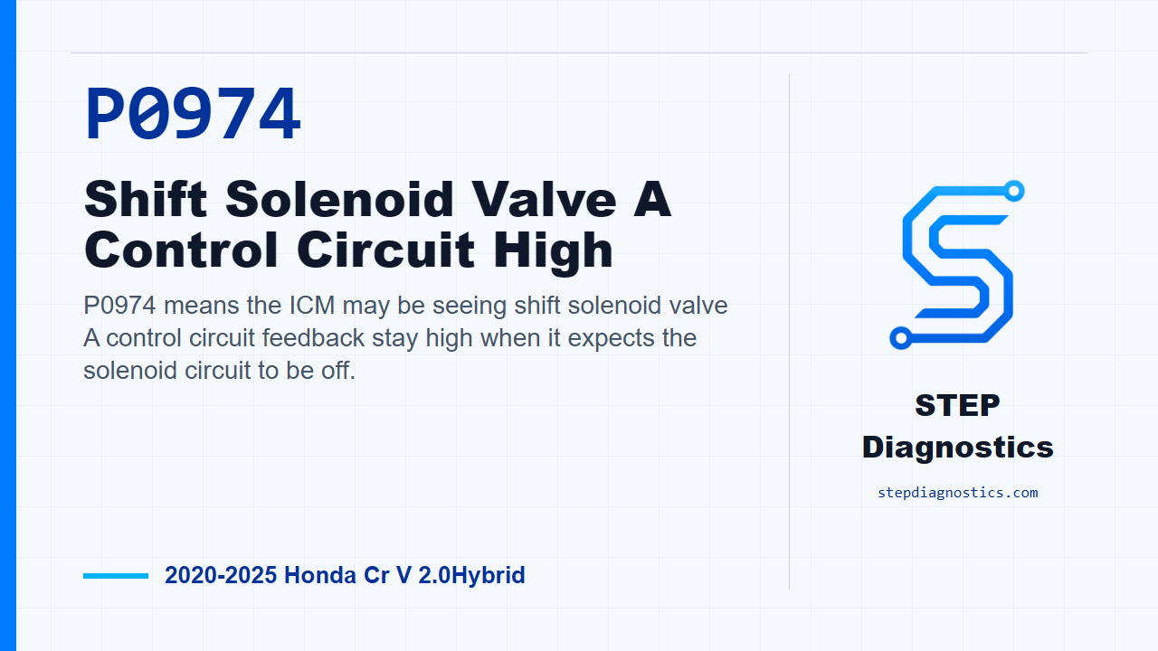
P0974 means the ICM may be seeing shift solenoid valve A control circuit feedback stay high when it expects the solenoid circuit to be off.
What the vehicle may do
- The vehicle may turn on a warning light.
- The vehicle can have possible transmission-related behavior.
- The code may store when the commanded solenoid state and the return signal do not agree.
Possible fault areas
- Possible shift solenoid valve A fault.
- Possible SH-A control circuit, wiring, or connector issue.
- Possible ICM issue after related checks are normal.
Diagnostic path
Opening and diagnostic frame
On this 2020 to 2025 Honda CR-V Hybrid, P0974 is for shift solenoid valve A control circuit high in the ICM system. In plain terms, the ICM may be commanding shift solenoid valve A off, but the return signal does not match what it expects. The driver may notice a warning light or possible transmission-related behavior, and the broad fault areas can include the solenoid, its control circuit and connectors, or the ICM. Before getting deep into testing, start with the basic system checks and follow a structured diagnostic approach. Also keep in mind that this path does not give a direct stand-alone component test for the solenoid itself; it diagnoses the related circuit behavior around it.
Reproduce the operating conditions
First, reproduce the operating conditions for the code. Turn the vehicle to READY TO DRIVE mode. Then shift the transmission to Park and wait for at least 1 second. That gives the ICM a chance to run the logic that compares the command to the return signal.
Shift solenoid valve A circuit simulation
Next, move into the shift solenoid valve A inspection. Disconnect the shift solenoid valve cover assembly connector, the 5P connector. Clear the ICM DTCs with the HDS. Then jump terminal No. 5 of that 5P connector to body ground with a jumper wire. After that, run the companion confirmation check. Do not treat the companion code as the main subject here; use it only as the expected response to this circuit simulation. If that expected response is present, this inspection is considered normal, and the diagnostic call is a problem with shift solenoid valve A. If the expected response is not present, the path points toward other related components instead of the solenoid call.
Check the SH-A circuit for an open
If the diagnostic path continues into the SH-A open-wire check, disconnect the shift solenoid valve cover assembly 5P connector and disconnect ICM connector P, the 36P connector. Then perform the table-based inspection for the SH-A circuit. The normal condition for the OFF check is less than 1 Ω. If that check is not normal, the problem is in the circuit. For this table, make sure the probe points are positively identified before testing; if the terminal identification is not clear, pause and recheck the earlier diagnostic path instead of guessing.
ICM conclusion
Only after the other inspection items indicate a normal condition does the path leave the remaining suspect as the ICM. At that point, the diagnostic result is a problem with the ICM. The important part is the order: confirm the operating condition, simulate the solenoid circuit response, check the SH-A circuit for an open, and only then make the ICM call if the earlier inspections are normal.
Takeaway
The takeaway on P0974 is to prove whether the ICM sees the expected circuit response before blaming the controller. Use the companion response as a circuit check, verify the SH-A wire is not open, and avoid jumping ahead when a connector or terminal callout is uncertain. For more diagnostic training, visit stepdiagnostics.com.
Final check
P0974 is often approached as an electrical control-circuit diagnosis: confirm the operating condition, simulate the expected response, check the circuit, and only then make a controller call if the IÃ
For more guided automotive diagnostics, visit STEP Diagnostics.