The fuel system on the 2020-2025 Honda CR-V 2.0 Hybrid has to do more than deliver gasoline. It must supply the direct-injection system, create and regulate high fuel pressure, meter fuel for each cylinder, and give the powertrain control module (PCM) enough feedback to judge mixture and cylinder-to-cylinder balance. A fault in one part of that chain can influence several scan-data values and set codes that describe pressure, mixture, post-catalyst correction, or cylinder variation.
For a mechanic, the useful starting point is not "Which part does this code name?" It is "Which fuel-system behavior failed, and what result will separate the likely causes?" A fuel-pressure code does not automatically condemn the high-pressure pump. A rich code does not prove that an injector is leaking. A cylinder air/fuel variation code does not identify the injector, ignition system, or mechanical condition by itself.
Applicability and service-information boundary
This overview applies to the STEP Diagnostics vehicle profile for the 2020-2025 Honda CR-V 2.0 Hybrid. Source endpoints confirm a 2020 CR-V 4WD with the 2.0L LFB2 hybrid engine and a 2025 CR-V 4WD with the 2.0L LFC3 hybrid engine. The detailed source procedures reviewed for this overview are for the exact 2025 LFC3 target.
The high-level system and diagnostic categories below are educational. Exact pressure values, scan-tool commands, monitor conditions, connector details, component locations, fuel-pressure relief steps, high-voltage isolation steps, and repair procedures must come from the applicable service information for the vehicle being repaired.
What the fuel system does
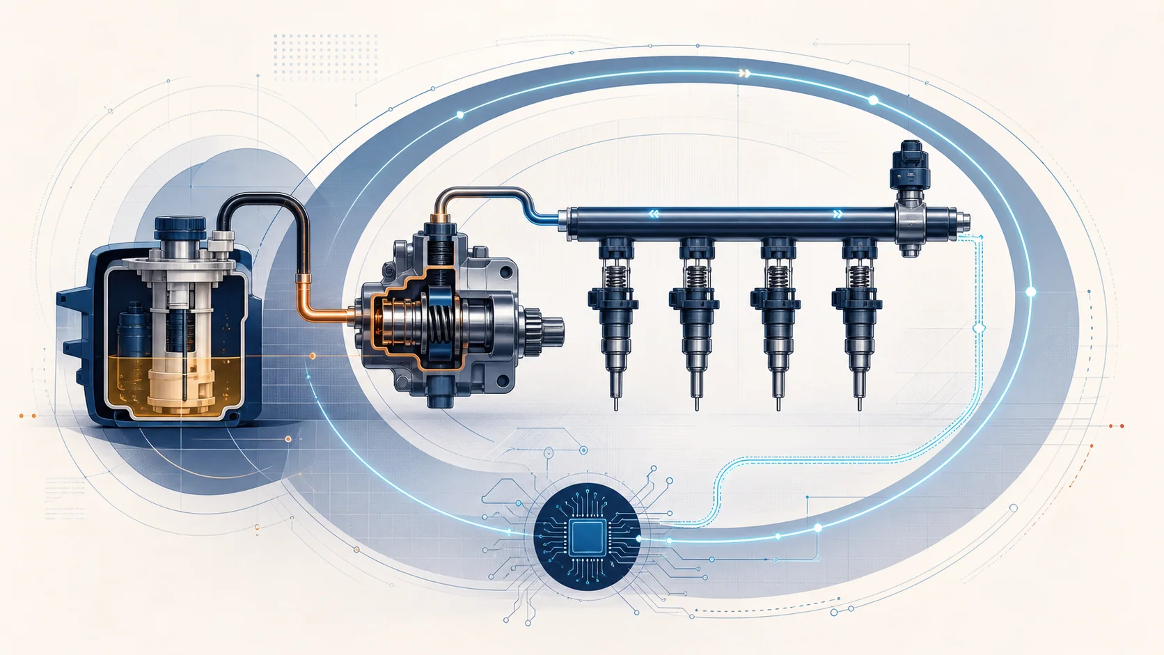
The system can be understood as five connected functions:
- The in-tank side supplies fuel from the tank toward the engine.
- A mechanically driven high-pressure pump raises fuel pressure for direct injection.
- The fuel rail distributes high-pressure fuel to the injectors, while the rail-pressure sensor reports actual pressure to the PCM.
- The PCM commands pressure control and injector delivery for the current operating condition.
- Airflow, air/fuel, oxygen-sensor, and cylinder-balance feedback help the PCM judge whether delivered fuel produced the expected result.
This is a feedback-controlled system. The PCM has a target, commands the system, observes actual pressure and combustion-related feedback, and adjusts. Diagnosis should follow the same loop: identify the failed behavior, command or reproduce it under the applicable conditions, measure the response, and use that result to choose the next test.
Main functional areas
| Functional area | What it contributes | What a mechanic should prove |
|---|---|---|
| Low-pressure supply | Moves fuel from the tank to the engine-side high-pressure system | Fuel is present, the supply side can deliver it, and no leak, restriction, electrical supply problem, or incorrect fuel condition is driving the complaint |
| High-pressure generation | The camshaft-driven high-pressure pump raises pressure for direct injection | The pump is being supplied, its mechanical drive is sound, control is available, and actual pressure follows the applicable target |
| Rail pressure feedback | Reports the pressure available to the injectors | The signal is plausible and agrees with the rest of the pressure-control evidence before a pump or sensor is condemned |
| Injector metering | Delivers the commanded quantity to each cylinder | Electrical control, flow behavior, sealing, and cylinder-to-cylinder contribution are separated from ignition and mechanical causes |
| Mixture and exhaust feedback | Uses upstream air/fuel and downstream oxygen information to judge mixture control and post-catalyst behavior | Airflow, exhaust integrity, sensor response, purge influence, fuel quality, and upstream combustion faults are considered in the right order |
| Cylinder-balance analysis | Compares the fuel behavior of individual cylinders | The affected cylinder is confirmed, then compression, manifold condition, ignition, and injector behavior are isolated instead of guessed |
Common failure categories and possible symptoms
Supply or pressure-generation faults
For a low-pressure fault such as P0087, low supply, a restriction, an electrical feed problem, a rail-pressure signal problem, wear in the pump drive, or a high-pressure pump/control fault can prevent actual rail pressure from following the target. Depending on the operating condition, the vehicle may illuminate the malfunction indicator, hesitate, lose power, start poorly, stall, or show little obvious complaint beyond stored data.
Pressure that is too high is a different failure direction. For P0088, resolve the related faults identified by the applicable procedure first, then use the directed high-pressure-supply test and let that result control the next action. Do not apply the P0087 isolation sequence to every pressure code.
Rich-mixture faults
A rich correction can come from more than excessive commanded fuel. Pressure control, airflow measurement, air/fuel feedback, injector behavior, fuel quality, unwanted purge flow, or fuel contamination of the engine oil can influence the result. The vehicle may run rough, have poor fuel economy, or stall under the applicable conditions.
Post-catalyst correction faults
A post-catalyst rich-trim code is not automatically a failed downstream sensor or catalyst. Related upstream mixture, injector, sensor, and misfire faults can change what the exhaust sensors report. Exhaust leakage or restriction in the monitored section also matters. Clear prerequisite faults and inspect the exhaust path before treating the post-catalyst code as an isolated part failure.
Cylinder air/fuel variation
Cylinder-specific variation means the PCM sees one cylinder behaving differently from the expected balance. Possible categories include injector behavior, ignition or misfire faults, compression, and intake or exhaust manifold condition. The code identifies the cylinder and the failed comparison; it does not prove which category caused it.
A practical diagnostic strategy
1. Preserve the evidence
Record the complete code set, status, available snapshot or freeze-frame data, fuel-pressure data, fuel-trim direction, relevant sensor values, and the customer complaint before clearing anything. Note whether the concern appears during engine start, steady running, acceleration, transition between electric and engine operation, or a specific temperature/load condition.
2. Classify the failed behavior
Separate the case into pressure too low, pressure too high, overall mixture rich, post-catalyst correction, or cylinder-specific variation. If several categories are present, determine which code or system fault is a prerequisite in the applicable procedure. Do not let a later consequence become the first repair target.
3. Make the work area safe
Inspect for an active fuel leak before testing. Fuel is flammable and the direct-injection side can retain pressure. Use the applicable pressure-relief and line-handling procedure before opening the system. Because this is a hybrid vehicle, follow the applicable high-voltage work boundary and isolation procedure whenever the repair area or service operation requires it.
4. Compare command with response
For a low-pressure fault, use the applicable scan-tool function and service procedure to compare requested behavior with actual fuel-pressure response. If the response is wrong, separate low-side delivery, electrical supply, rail-pressure feedback, pressure control, mechanical pump drive, and the pump itself. For a high-pressure fault, resolve the directed related faults first and follow the applicable high-pressure-supply test instead of reusing the low-pressure path. One abnormal result should choose the next test; it should not trigger replacement of every component in the chain.
5. Check what can bias mixture judgment
For a rich or post-catalyst fault, first resolve related pressure, airflow, air/fuel-sensor, oxygen-sensor, injector, ignition, and misfire codes. Then evaluate airflow plausibility, fuel-trim direction, pressure-control results, purge influence, oil contamination, fuel quality, exhaust integrity, and sensor response as directed by the applicable procedure.
6. Isolate a cylinder-specific variation
For P219C or P219E, confirm the cylinder identified by the code under the applicable conditions. Establish the mechanical baseline with the directed compression check. Inspect relevant manifold condition, then use the applicable injector-isolation method to see whether the fault follows the injector. Keep ignition and related misfire evidence in the same decision path.
7. Reassess after every result
Treat each test as one result from the vehicle. Re-read the case state after that result, then choose the next step. If a leak is repaired, a pressure response becomes normal, or a cylinder fault moves during an isolation test, reassess the full code set and symptom before continuing.
8. Verify the repair
After the confirmed cause is corrected, inspect every disturbed fuel connection, restore the vehicle according to the applicable procedure, clear codes only at the correct point, and repeat the relevant confirmation conditions. Confirm the pressure or feedback behavior is now normal, the original symptom is gone, related monitors or code status complete as required, and no new fault was introduced.
Related STEP Diagnostics guides
| Guide | Failed behavior | Diagnostic focus |
|---|---|---|
| P0087 | Actual high-side pressure is lower than the system expects | Prove supply, pressure feedback, pump control, mechanical drive, and high-pressure generation in sequence |
| P0088 | Rail pressure is higher than the commanded or expected range | Resolve the directed related faults first, then use the applicable high-pressure-supply test to determine the next action |
| P0172 | Overall mixture correction has moved rich | Confirm the condition, then evaluate pressure, airflow, oil/PCV influence, purge, fuel quality, sensor feedback, and injectors in the applicable order |
| P2097 | Post-catalyst fuel-trim judgment is rich | Resolve upstream faults, inspect the monitored exhaust path, and use the result to separate exhaust and sensor direction |
| P219C | Cylinder 1 air/fuel behavior differs from the expected balance | Confirm cylinder 1 variation and isolate mechanical, manifold, ignition, and injector causes |
| P219E | Cylinder 3 air/fuel behavior differs from the expected balance | Confirm cylinder 3 variation and isolate mechanical, manifold, ignition, and injector causes |
Repair categories
The final repair may involve a leak or damaged connection, low-side supply or electrical repair, a pressure sensor or circuit, high-pressure pump control, mechanical pump drive, a high-pressure pump, an injector, contaminated fuel or oil, purge control, an airflow or exhaust-feedback sensor, an exhaust leak/restriction, ignition repair, or another confirmed mechanical condition.
The category is not the conclusion. The conclusion comes from the test result that isolates the cause, followed by a repair verification that reproduces the original operating condition without the fault.
Safety reminder
Do not open a pressurized fuel system, test for leaks with an ignition source, or work in a hybrid high-voltage area without the applicable service procedure, tooling, protective equipment, and qualification. After any fuel-system repair, inspect for leakage before returning the vehicle to service.
Use this overview to organize the case. Use the linked STEP guides for code-specific direction, and let the applicable service information control the exact procedure for the vehicle in front of you.