What this code means
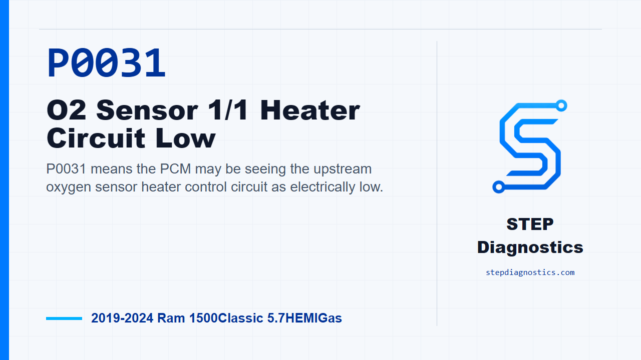
P0031 means the PCM may be seeing the upstream oxygen sensor heater control circuit as electrically low.
What the vehicle may do
- The MIL may illuminate.
- The PCM can disable the oxygen sensor heater driver for the rest of the ignition cycle.
- The vehicle may have limited noticeable drivability symptoms, but cold-start emissions control and readiness behavior can be affected.
Possible fault areas
- A possible heater control circuit short to ground.
- A possible short between the heater control circuit and the oxygen sensor ground circuit.
- Possible connector, terminal, harness, or water intrusion issues.
- Possible oxygen sensor heater circuit concern.
- Possible PCM heater driver concern.
Diagnostic path
Code overview and starting point
On this Ram 1500 Classic with the 5.7 HEMI, P0031 means the PCM is seeing the upstream oxygen sensor heater control circuit on sensor 1/1 as low. In plain terms, the heater side of that sensor circuit may be pulled too low electrically. The MIL may be on, and the PCM can disable that heater driver for the rest of the ignition cycle. Vehicle symptoms may be limited, but cold-start emissions control and readiness behavior can be affected. Broadly, we’re looking at a possible grounded heater control circuit, a heater control circuit shorted into the sensor ground, a connection problem, the sensor heater circuit, or the PCM driver. Start with the basic system checks, then verify the code is current before doing pinpoint electrical testing.
Monitor gate and set condition
For this monitor to run, battery voltage has to be between 10.5 and 15.75 volts, the O2 sensor heater is commanded on, and the heater circuit high fault is not active. The code sets when the PCM detects the O2 Sensor 1/1 heater circuit resistance below approximately 2.0 Ohms. Treat those as the operating gates and the diagnostic formula. The video can show the circuit path and decision points, but the key idea is simple: prove whether the low condition is in the wiring, the sensor side, the connection path, or the PCM driver control.
Confirm the fault before testing
First, scan all modules, record the codes and the environmental data, and save the scan report and related data. Clear the codes, turn the ignition off for a minimum of 10.0 seconds, then turn the ignition back on. Reproduce the operating conditions using the captured data and the monitor conditions, then read codes again. If P0031 comes back, continue with the circuit test. If it does not come back, treat it as an intermittent condition instead of forcing a hard-fault diagnosis.
Check the heater control circuit for a short to ground
With the ignition off, disconnect the O2 Sensor 1/1 connector and disconnect the PCM C2 connector. Now check continuity between ground and the O2 Sensor 1/1 K99 heater control circuit at the sensor harness connector. If there is continuity, repair the K99 heater control circuit for a short to chassis ground or a short into the O2 Sensor Z908 ground circuit, then verify the repair and confirm the code stays gone. If there is no continuity, move on to checking PCM heater control operation.
Check PCM heater control driver operation
Reconnect the PCM connector, leave the O2 sensor connector available for testing, and turn the ignition on. Command the O2 Sensor 1/1 control to the maximum allowable percentage with the scan tool. Using a 12-volt test light connected to ground, probe the K99 heater control circuit at the O2 Sensor 1/1 harness connector. With the actuator on, the test light should illuminate, and the brightness depends on the actuation percentage selected. Then command the Oxygen Sensor 1/1 control to the OFF (0%) position and probe the same circuit again. With the actuator off, the test light should not illuminate. If the light behaves correctly on and off, replace the O2 Sensor 1/1, then verify the repair and confirm the code stays gone. If the light does not behave that way, continue to the connection checks.
Inspect related PCM and component connections
At this point, address any applicable bulletins, then shut the system down and inspect the related connection path. Disconnect the PCM connectors, any related in-line connectors if equipped, and the related component connectors. Look closely for poor connector installation, damaged locks, corrosion, water intrusion, seal damage, bent terminals, signs of overheating from a poor connection, terminals pushed back in the cavity, spread terminals, and weak terminal tension. Repair any conditions found. Then reconnect the PCM, in-line connectors if equipped, and the related component connectors, making sure everything is fully seated and locked.
Retest after connection work
After the connector and terminal work, clear the codes. Test drive or operate the vehicle under the monitor and set conditions, then read codes again. If P0031 returns after those checks, replace and program the PCM, then verify the repair and confirm the code stays gone. If the code does not return, the wiring or poor connection problem has been repaired, and you still finish by verifying the repair.
Takeaway
The clean diagnostic path for P0031 is to confirm the code is current, check the heater control circuit for a short to ground, prove the PCM driver command with the test light, then inspect and repair the connection path before condemning the PCM. Verify the repair separately and make sure the code stays gone. For more diagnostic training, visit stepdiagnostics.com.
Final check
This diagnosis often comes down to separating a wiring short, a sensor-side issue, a connection fault, and PCM driver control before making the repair decision.
For more guided automotive diagnostics, visit STEP Diagnostics.