Applicability basis: Authorized vehicle records confirm Ram 1500 Classic Truck 4WD applications with the 5.7-liter gasoline engine at the 2019 and 2024 endpoints. Detailed system operation and diagnostic evidence for this overview was verified on the 2024 application. Exact thresholds, sensor locations, circuit details, test values, scan-tool functions, and service procedures can vary by model year and calibration; use current service information for the truck being repaired.
What the knock sensor system does
Combustion pressure should rise in a controlled way after the spark plug fires. Knock is abnormal auto-ignition of the remaining air-fuel mixture after normal combustion has started. The rapid pressure rise creates vibration that can reduce performance and, if it is severe and continuous, damage the engine.
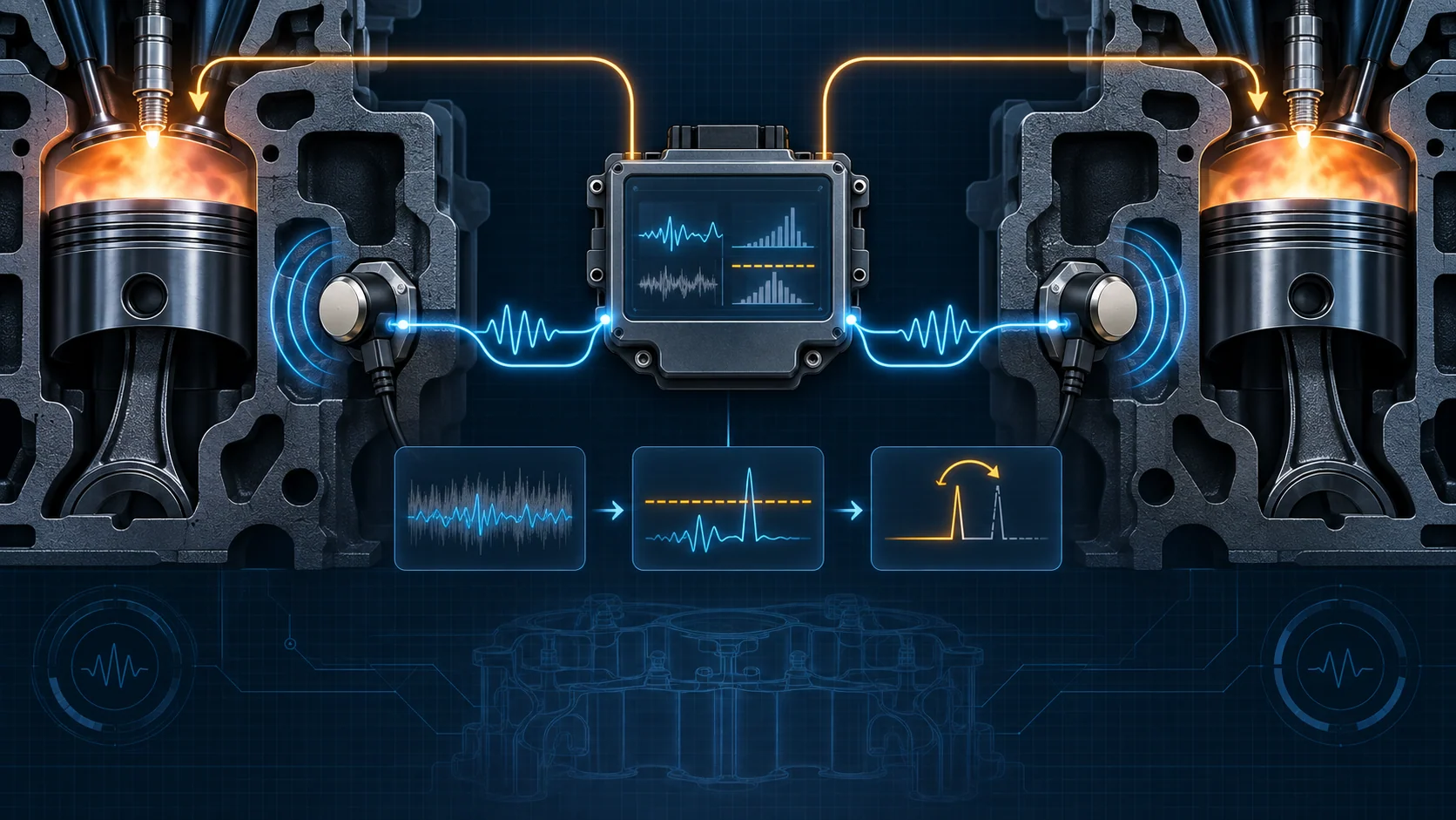
The knock sensors listen for vibration through the engine structure. They do not identify bad fuel, carbon deposits, overheating, a loose connector, or a damaged engine part by themselves. Their electrical output represents vibration strength, while the powertrain control module (PCM) decides whether that signal looks like combustion knock for the current operating condition.
How the PCM separates knock from normal engine noise
A running engine is never vibration-free. Normal valvetrain, piston, accessory, combustion, and rotating-assembly activity produces background noise, so knock-sensor voltage does not simply fall to zero when knock is absent. Background noise also changes with engine age, temperature, speed, load, and operating condition.
The PCM accounts for that changing background and evaluates the sensor signal against a calibrated threshold when the engine is operating where knock is possible. When the signal exceeds what the strategy expects, the PCM can reduce spark advance. If knock continues, it can apply additional correction. When the event stops, the strategy can recover timing rather than permanently leaving the engine heavily retarded.
This feedback allows the engine to operate near efficient spark timing while retaining protection against knock. It also explains why a sensor waveform or scan value must be interpreted with engine speed, load, temperature, fuel quality, noise, and the complete DTC set.
What P0325 and P0330 actually mean
| DTC | Diagnostic direction | What it tells you to prove |
|---|---|---|
| P0325 | Knock Sensor 1 circuit signal is electrically outside the expected range | Sensor 1 signal and return circuits, connector integrity, sensor condition, and PCM responsibility in the directed order |
| P0330 | Knock Sensor 2 circuit signal is electrically outside the expected range | Sensor 2 signal and return circuits, connector integrity, sensor condition, and PCM responsibility in the directed order |
These are circuit-monitor codes. Neither code proves that the engine is experiencing destructive knock, and neither code proves that the sensor itself has failed. An open circuit, excessive resistance, short to ground, short to voltage, signal-to-return short, poor terminal contact, water intrusion, damaged harness, sensor problem, or much less commonly a PCM problem can produce an electrical fault.
The opposite distinction matters too: real audible knock can exist without P0325 or P0330 if the circuits remain electrically plausible. Diagnose the sound and the electrical code as related but separate questions.
What the driver or technician may notice
- a steady malfunction indicator lamp;
- reduced power or softer throttle response if the PCM uses conservative spark timing;
- an intermittent code that appears only at a particular speed, load, temperature, or vibration level;
- no obvious drivability complaint even though a pending or stored circuit fault is present;
- audible pinging or rattling under load from a real combustion or mechanical condition;
- a fault that began after intake, engine, harness, connector, or sensor work.
Symptoms do not identify the failed part. A truck can have a clean-running engine with an electrical knock-sensor fault, or a serious audible knock with no knock-sensor circuit code.
Common failure categories
Signal or return circuit faults
Opens, high resistance, rubbed insulation, pinched wiring, shorts to ground or voltage, and a short between the signal and return paths can move the circuit outside the PCM's expected range. Harness movement, engine torque, heat, and moisture can make the fault intermittent.
Connector and terminal problems
Loose engagement, spread or backed-out terminals, damaged locks or seals, corrosion, water entry, and previous probing damage can create unstable contact. Inspect both halves of the connection and preserve terminal tension. Do not force oversized probes into control-module or sensor terminals.
Sensor installation or sensor failure
A damaged sensor can produce an implausible signal, but mounting and contact with the engine are part of how a vibration sensor works. Incorrect installation, contamination at the mounting surface, impact damage, or incorrect fastener handling can change response. Follow the exact service procedure rather than treating the sensor like a generic threaded switch.
Real combustion knock
Low-octane or contaminated fuel, excessive combustion temperature, heavy load, excessive spark advance for the condition, deposits, cooling problems, mixture or airflow faults, and other engine conditions can promote real knock. Correcting an electrical circuit fault does not repair a separate combustion cause.
Mechanical or accessory noise
Loose components, valvetrain or rotating-engine damage, an exhaust contact, belt-drive noise, or another structural vibration can imitate or mask a knock event. A severe new engine noise requires a safe mechanical inspection before extended loaded operation.
PCM responsibility
The PCM belongs at the end of the directed path. Verify powers, grounds, connectors, wiring, sensor installation, and repeatable test results before considering controller replacement or programming.
A practical system-first diagnostic strategy
1. Preserve the evidence
Confirm the exact year, engine, drivetrain, calibration, fuel, recent repairs, and current service information. Save the complete module scan, confirmed/pending/history codes, freeze-frame or failure-record data, and the conditions under which the complaint occurs before clearing anything.
2. Decide whether the engine is safe to run
If there is severe metallic knock, low oil pressure, overheating, heavy misfire, sharp power loss, or another sign of possible engine damage, stop loaded testing. A scan-tool reproduction step is never more important than preventing engine or catalyst damage.
3. Separate circuit plausibility from real knock
Ask two questions: is the PCM reporting an electrically implausible knock-sensor channel, and is the engine actually knocking or producing abnormal mechanical noise? P0325 and P0330 answer the first question. Fuel, temperature, load, sound, and mechanical evidence answer the second.
4. Classify active versus intermittent behavior
Use stored operating data and the current service procedure to reproduce the original region safely. If the code is active, continue with directed circuit checks. If it is not active, inspect and stress the relevant harness and connections while watching for a repeatable change rather than replacing parts from history alone.
5. Inspect before disconnecting everything
Look for recent engine work, trapped or stretched wiring, heat damage, fluid contamination, loose connectors, damaged locks, missing retainers, contact with brackets, and evidence of water entry. Photograph and label routing before disturbing it.
6. Prove the circuit in the specified order
Use the exact wiring diagram and terminal-safe test method for the truck. Verify the signal and return paths for opens or excessive resistance, shorts to ground or voltage, and a short between the two paths. Keep connector inspection separate from conductor testing so an intermittent terminal fault is not missed.
7. Evaluate the sensor only after circuit integrity is known
Confirm the correct sensor, installation, mounting surface, and service procedure. If directed testing supports replacement, retest under the original conditions before moving to the PCM. Replacing both sensors because one circuit code set discards useful diagnostic evidence.
8. Verify the complete repair
Restore routing, retainers, seals, connectors, and any removed engine components exactly as required. Clear codes only when directed, repeat the relevant self-test or operating condition, and confirm that no pending or confirmed knock-sensor circuit DTC returns. If audible knock was part of the complaint, verify that its fuel, cooling, combustion, or mechanical cause is also resolved.
A cleared lamp or a short idle without a reset is not repair verification.
Safety and service cautions
Running tests place the technician near the fan, belts, pulleys, hot exhaust parts, and high-temperature engine surfaces. Secure clothing, leads, and tools and keep clear of moving parts. Do not create a knock event by striking the engine or sensor, and do not use an improvised impact test as proof of sensor health.
Use terminal-safe adapters and back-probing methods permitted by current service information. Disconnecting or probing the wrong control-module terminal can create a new fault. If sensor access requires intake or fuel-system work, follow the specified pressure-relief, cleanliness, sealing, and fire-safety procedures before disassembly.
Final takeaway
The 2019-2024 Ram 1500 Classic 5.7L HEMI Gas knock sensor system is a vibration-feedback system that helps the PCM protect the engine while keeping spark timing efficient. The PCM learns normal background noise, evaluates both sensor channels in operating context, and can reduce spark advance when it recognizes knock.
P0325 and P0330 are electrical circuit directions, not automatic proof of bad sensors or destructive combustion knock. Preserve operating evidence, decide whether continued running is safe, separate real noise from circuit plausibility, inspect the harness and terminals, prove both signal and return paths, and move to the sensor and PCM only when the directed results support it. Finish by reproducing the original condition and confirming that both the electrical fault and any real knock complaint are gone.