What this code means
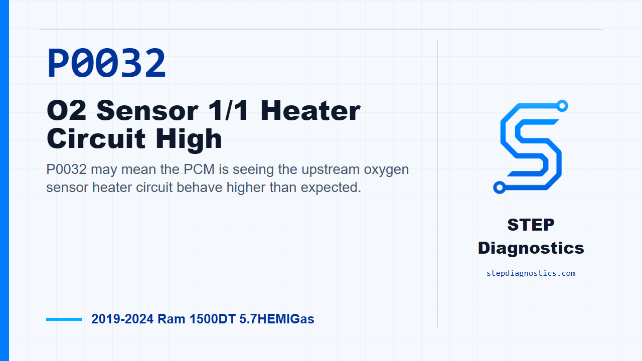
P0032 may mean the PCM is seeing the upstream oxygen sensor heater circuit behave higher than expected.
What the vehicle may do
- The MIL may illuminate.
- Oxygen sensor warm-up may be affected.
- Fuel-control behavior may be affected while the sensor heater is not operating as expected.
Possible fault areas
- Possible heater control circuit fault.
- Possible sensor ground fault.
- Possible connector or terminal issue.
- Possible oxygen sensor fault.
- Possible PCM control issue.
Diagnostic path
Opening context
On this Ram 1500, P0032 is for the O2 Sensor 1/1 heater circuit high. In plain language, the PCM may be seeing the upstream oxygen sensor heater circuit acting higher than expected. The truck may turn the MIL on, and oxygen sensor warm-up or fuel-control behavior may be affected. Possible fault areas can include the heater control wiring, the sensor ground, connector or terminal issues, the oxygen sensor itself, or, less often, the PCM. If other codes are present, check what they mean first, then keep this diagnostic path focused on P0032. Start with the basic system checks before diving into circuit testing.
Sensor and heater behavior to keep in mind
Before the circuit checks, keep the sensor behavior in mind so the scan data makes sense. Normal range of the O2 Sensor output is a 0 to 1.0 volt Analog to Digital, or A/D, signal. Each O2 Sensor Return circuit has a 2.5 volt bias, and on a normally functioning sensor, the biased signal voltage should switch between 2.5 and 3.5 volts. If the heater is disabled, the affected O2 Sensor biased signal voltage can read high, usually stays above 4.0 volts. Also remember that heater circuit resistance can skew what you see. A small amount of resistance, 3-4 Ohms, may not set a Heater Control Circuit DTC. A heater circuit with 4.0 - 5.0 Ohms resistance can increase the heater temperature reading on the scan tool for the affected sensor by as much as 700°F. As little as 2.0 Ohms can increase the temperature reading approximately 250°F on the scan tool. On a normally operating switching O2 sensor, the typical duty cycle percentage will range between approximately 30 and 50 percent, and the typical heater temperature will range between approximately 1200°F and 1400°F on the scan tool. When the PCM disables the heater driver, the duty cycle will be 0 percent.
What has to happen for the code to set
Before testing, understand the monitor. This fault is checked when battery voltage is between 10.5 and 15.75 volts, the O2 sensor heater is commanded on, and the heater circuit low fault is not active. P0032 sets when the PCM detects O2 Sensor 1/1 heater circuit resistance above approximately 35.0 Ohms. When that happens, the MIL will illuminate, and the PCM will disable the O2 sensor heater driver for the rest of that ignition cycle.
Check bulletins, updates, and confirm the fault
First, check for any applicable service bulletins or PCM software updates related to P0032. If one applies, perform that repair or update, then verify the repair and confirm the code stays gone. If nothing applies, use the scan tool to read DTCs in all ECUs, record them, and record the environmental data tied to the fault. Erase the codes, turn the ignition off for a minimum of 10.0 seconds, then turn the ignition back on. Use the recorded environmental data and the monitor conditions to operate the vehicle in the same kind of conditions that set the code. Read the codes again. If P0032 returns, continue with the circuit tests. If it does not return, treat it as an intermittent condition.
Load test the sensor ground circuit
Next, load test the O2 sensor ground circuit. Disconnect the component harness connector to isolate the ground circuit. Connect the positive lead of the load test tool to battery positive, and connect the negative lead to the ground circuit at the component harness connector. A proper load test matters here. A 3156 bulb has approximately 6.0 Ohms of resistance when powered and draws approximately 2.0 amps. Many high-impedance test lights draw less than 0.1 amps and are not reliable for this kind of load test. The tool should draw more than approximately 0.75 amps. The bulb should be illuminated and bright, and the brightness should compare to a direct battery connection. If the bulb is bright, move on to the heater control circuit. If it is not bright, repair the ground circuit for an open or high resistance, then verify the repair and confirm the code stays gone.
Check the heater control circuit for a short to another circuit
With the ground circuit passing the load test, isolate the O2 Sensor 1/1 heater control circuit and check it for a short to another circuit at the PCM harness connector. The ignition must be off for this resistance check. Disconnect the ECU and every component connector that contains the circuit being tested, and leave the in-line connectors connected at this point. Use the wiring path to follow the circuit. Connect one DVOM lead to the circuit at the ECU harness connector, then probe the other circuits at that connector with the other lead. Do not probe PCM harness connector terminals directly. If a PCM terminal must be accessed, use the GPEC Diagnostic 10436 adapter. With the circuit isolated, there should be no continuity between the circuit being tested and any other circuit. If continuity is found, repair the short between those circuits, using in-line connectors to help narrow the location, then verify the repair and confirm the code stays gone. If there is no continuity, continue to the open or high-resistance check.
Check the heater control circuit for open or high resistance
Now check the same heater control circuit for an open or high resistance. The ignition must be off when checking circuit continuity. Isolate the circuit by disconnecting the ECU and the component harness connector. Before measuring the circuit, measure the resistance between the two DVOM leads so you know what the meter leads are contributing. Then measure the circuit from the component harness connector to the GPEC adapter. If a PCM terminal has to be accessed, use the GPEC Diagnostic 10436 adapter, and remember that the adapter can add up to 1.5 Ohms of resistance to the circuit. The decision point is whether the circuit resistance is below 3.0 Ohms. If it is below 3.0 Ohms, go to the PCM heater control driver test. If it is not below 3.0 Ohms, repair the circuit for an open or high resistance, then verify the repair and confirm the code stays gone.
Command the heater driver and watch the circuit response
If the wiring checks pass, test PCM heater control driver operation. Turn the ignition off, reconnect the PCM C2 harness connector, then turn the ignition on. Use a 12-volt test light connected to ground and probe the O2 Sensor 1/1 heater control circuit at the O2 sensor harness connector. With the scan tool, actuate the O2 Sensor 1/1 control to the maximum allowable percentage. The test light should illuminate, and its brightness will depend on the actuation percentage selected. Then command the actuator OFF, at 0%, and the test light should not be illuminated. If the light responds correctly with the actuator on and off, replace the O2 Sensor 1/1, then verify the repair and confirm the code stays gone. If the light does not respond correctly, continue to connector and PCM-related checks.
Inspect related connections before condemning the PCM
Before making a PCM call, inspect the related connections carefully. Perform any applicable bulletin first. Disconnect all PCM harness connectors, any related in-line harness connectors if equipped, and the related component connectors. Inspect the harness connectors, component connectors, and male and female terminals for proper installation, damaged locks, corrosion, signs of water intrusion, weather seal damage if equipped, bent terminals, overheating from a poor connection, pushed-back terminals, spread terminals, and terminal tension. Repair any condition found. Reconnect the PCM connectors, in-line connectors, and component connectors, making sure they are fully seated and the locks are fully engaged. Erase the codes, then test drive or operate the vehicle under the monitored and set conditions. Read the codes again. If P0032 returns after those connection checks, replace and program the PCM, then verify the repair and confirm the code stays gone. If it does not return, the wiring or poor connection problem has been repaired, and you still finish by verifying the repair.
Takeaway
The clean way through P0032 is to prove the ground can carry load, prove the heater control circuit is not shorted and is not open or high resistance, then command the driver and make the final call from the circuit response. Do not skip connector inspection before condemning the PCM. For more diagnostic training, visit stepdiagnostics.com.
Final check
P0032 is often best approached as an electrical heater circuit diagnosis before making a parts call.
For more guided automotive diagnostics, visit STEP Diagnostics.