Knock feedback helps the engine controller balance ignition timing against damaging combustion knock. On the 2019–2024 Ram 1500DT 5.7 HEMI gas engine, a knock-sensor circuit fault and actual engine knock are different diagnostic problems: a circuit code does not prove that the engine is detonating, and audible knock does not prove that a sensor has failed.
This educational introduction covers STEP's Ram 1500DT 5.7 HEMI library, not the separately cataloged 1500 Classic. Source checks include an early non-eTorque configuration and a later eTorque configuration. Match the actual model year, engine, drivetrain, eTorque equipment and PCM variant before selecting wiring, test adapters, monitor conditions or repair procedures. Endpoint configuration checks support the high-level explanation; they do not establish identical service details for every intervening vehicle.
Purpose and operation
Combustion knock can occur when part of the remaining air/fuel mixture auto-ignites after normal combustion has begun. Excessive ignition advance, high engine temperature and heavy load can contribute. Fuel quality and carbon deposits are other possible contributors; none is a diagnosis by itself.
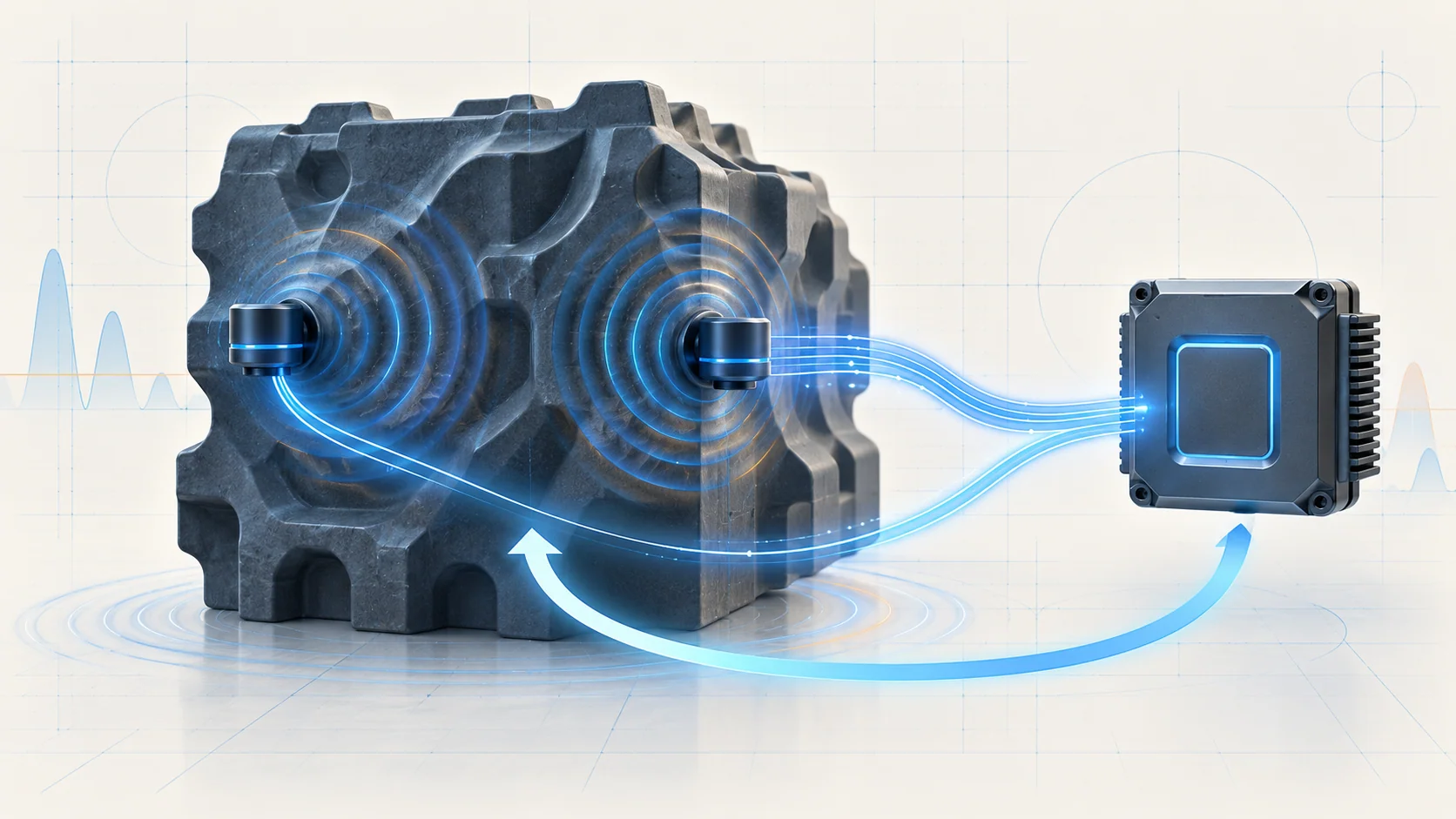
The knock sensors provide analog information about engine vibration to the powertrain control module (PCM). A running engine produces background noise even without knock. That background changes with speed, temperature, load and engine condition, so a nonzero sensor signal is not automatically evidence of abnormal combustion.
The controller uses learned background behavior and calibrated detection criteria to distinguish a knock event from ordinary engine noise. When it detects knock, it reduces spark advance according to the event's severity. As the condition subsides, timing compensation is recovered according to the calibration. This feedback supports engine protection and performance; it cannot compensate indefinitely for an underlying fuel, temperature or mechanical problem.
Main elements
The useful diagnostic model is a physical vibration input, a sensor signal path and a controller decision. The two monitored sensor channels have signal and return circuits. Sensor-to-controller wiring and connector integrity therefore matter as much as the sensor itself.
Do not infer physical sensor location, cylinder-bank mapping or interchangeability from the channel number alone. Use the applicable component identification and wiring information. Likewise, knock compensation is a controller response, not a direct measurement of a failed part.
What P0325 and P0330 tell you
P0325 — Knock Sensor 1 Circuit directs attention to the first monitored channel. The applicable source procedure checks abnormal electrical input and lists signal/return opens, shorts, sensor and controller faults as possible causes.
P0330 — Knock Sensor 2 Circuit addresses the second monitored channel. It requires the correct channel's wiring and service procedure, not a copied pin assignment from P0325.
These codes identify a detected circuit behavior, not a proven failed sensor and not proof of audible detonation. The exact electrical limits, enabling conditions and fault logic are configuration-specific. Start with the appropriate STEP guide and then use the service information for the actual vehicle.
Failure categories and symptoms
An open or high-resistance signal or return path can interrupt usable information. Shorts to another circuit, voltage, ground or the return path can also distort the input. Connector corrosion, water intrusion, damaged locks, backed-out terminals or poor terminal contact can create persistent or intermittent faults. A sensor fault remains possible; the controller is another possibility only after the applicable diagnostic path supports it.
An illuminated malfunction indicator lamp and a stored circuit code may be the main complaint. The absence of audible knock does not rule out an electrical fault. Conversely, a combustion-noise complaint without these codes needs its own investigation into operating conditions rather than an automatic knock-sensor replacement.
If acceleration feels different, do not assume knock feedback is the cause from that symptom alone. Review the complete scan, fuel-related evidence, temperature information and any other relevant engine faults. A change in timing data must be interpreted with the load and conditions under which it was recorded.
A practical diagnostic strategy
First preserve the evidence. Read all modules, record the DTCs and available environmental data, and save the scan report before erasing anything. Establish whether the reported code is current or intermittent and whether another problem needs priority. Apply the vehicle's pre-diagnostic procedure and check relevant service bulletins.
Next separate the complaint into an electrical-channel problem, a real combustion concern, or both. Note fuel history, engine temperature and the conditions in which the complaint occurs. Do not deliberately provoke severe knock to test the feedback system.
For a circuit code, identify the correct sensor channel and inspect its harness and connections. Look for damaged routing, corrosion, water entry, insecure locks and poor terminal retention. Similar-looking channels do not justify exchanging connectors or assuming identical pinouts.
Follow the applicable circuit tests for unwanted continuity and open/high-resistance paths. Resistance checks require ignition off and the specified circuit isolation. Meter leads and prescribed adapters can affect a measurement; apply the source procedure's allowance and acceptance criteria. Do not improvise a universal resistance limit or a jumper test.
Protect the PCM terminals. Where the procedure requires a diagnostic adapter, use it instead of probing the PCM harness connector directly. A test that damages terminal contact can create a new intermittent fault and undermine the original diagnosis.
Treat a sensor replacement as a supported step in the diagnostic path, not the first response to the DTC name. A controller replacement or programming operation needs the complete applicable procedure and supporting results. This overview does not reproduce the OEM decision-tree sequence.
Repair categories and verification
Repair may involve the proven wiring fault, connector or terminal condition, or a sensor identified by the applicable tests. A separate combustion problem may instead call for correcting a supported fuel, temperature or mechanical cause. Keep those repair categories distinct.
Sensor installation, access steps, mounting requirements and tightening specifications come from the exact service procedure. This overview does not provide a mounting torque or an access shortcut. Controller replacement, if actually justified, also requires the applicable installation and programming information.
After repair, ensure disturbed connections are seated and locked. Perform the required powertrain verification and operate the vehicle under the prescribed monitored conditions only when it is safe to do so. Recheck codes and the original complaint. Code clearing alone does not demonstrate that a circuit is reliable or that a combustion concern has been resolved.
Safety and scope
Allow hot components to cool before access, keep clear of moving belts and fans, and secure the vehicle for any work underneath it. Follow the relevant electrical isolation procedure before disconnecting or measuring circuits. eTorque-equipped vehicles need the applicable equipment-specific precautions; this overview is not an eTorque disable procedure.
Do not continue a high-load test through severe persistent knock, overheating or another condition that risks engine damage. Stop and investigate safely. The goal is a trustworthy feedback signal and a verified repair—not a disabled monitor, altered calibration or repeated code erasure.