What this code means
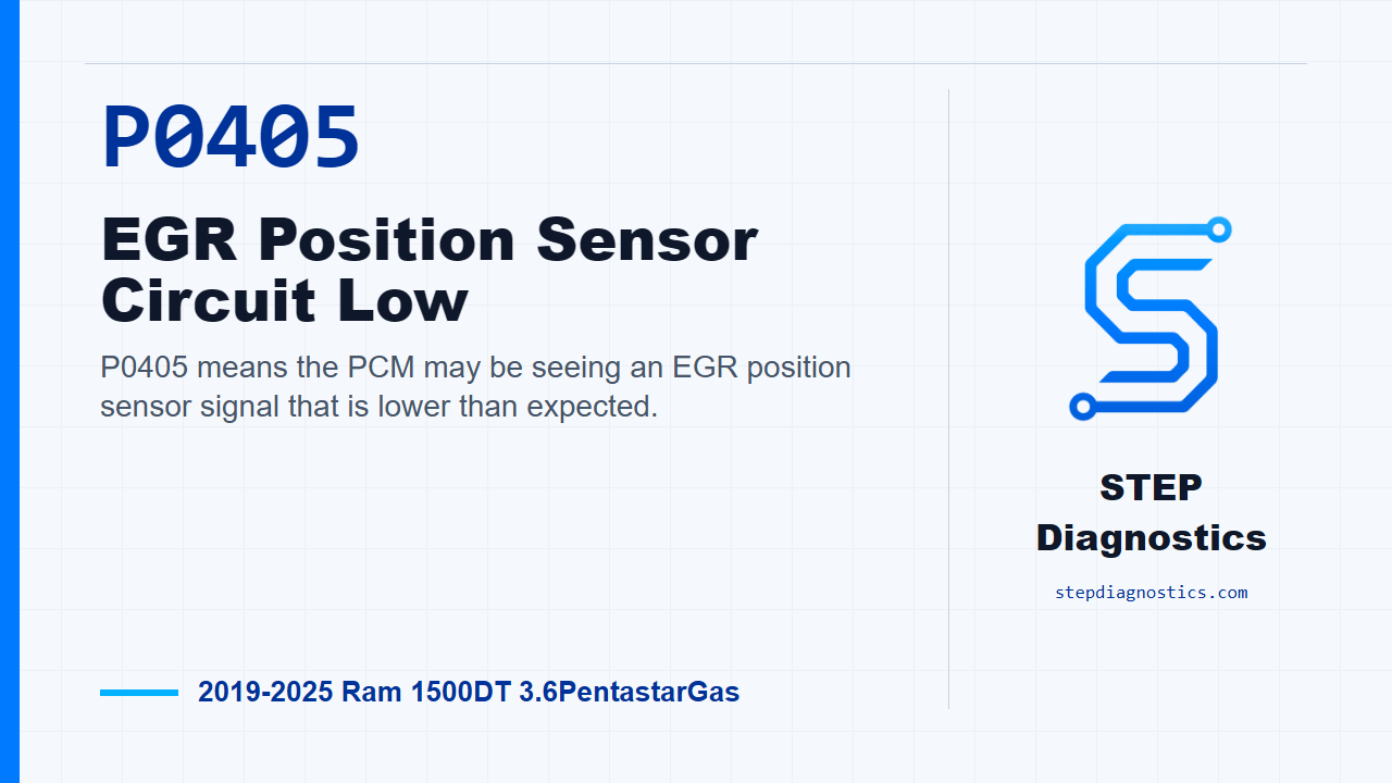
P0405 means the PCM may be seeing an EGR position sensor signal that is lower than expected.
What the vehicle may do
- The MIL may illuminate.
- The vehicle may have EGR-related drivability symptoms, depending on operating conditions.
Possible fault areas
- The EGR position signal circuit may be shorted low.
- The signal circuit may be interacting with the sensor ground circuit.
- The EGR valve assembly may have a position sensor concern.
- A PCM concern is possible after circuit and connection checks are completed.
Diagnostic path
Open and code meaning
On this Ram 1500 with the 3.6 Pentastar, P0405 means the PCM may be seeing the EGR position sensor signal too low. In plain terms, the module is not seeing a believable position signal from the EGR valve assembly. The MIL may be on, and the vehicle may have EGR-related drivability symptoms depending on operating conditions, but the diagnostic path here is electrical: possible signal circuit trouble, possible sensor ground interaction, a possible EGR valve assembly issue, or, after the circuit checks are finished, a possible PCM concern. Start with the basic system checks first. If other codes are present, check what they mean first, then come back to this circuit test.
How the PCM judges this fault
This is a three-wire EGR position sensor circuit: 5-Volt Supply, Sensor Signal, and Sensor Ground. The full range of travel of the shaft is approximately 5.0 mm from fully closed to fully open. Typically, the peak current draw by the EGR valve occurs during opening, and the maximum current load for a typical application is approximately 6.0 amps. After the valve opens, the duty cycle is adjusted so the typical average current draw is approximately 0.5 amps while holding the valve open. On the position side, full output shaft travel results in a change of approximately 3.9 volts in the sensor reading. During normal operation, the position sensor signal voltage ranges between approximately 0.5 volts closed and 4.3 volts open. For P0405, the PCM sets the fault when the EGR position sensor signal voltage is below 0.1 volts. The monitor runs with the ignition on, battery voltage above approximately 10.4 volts, and the ASD relay energized.
Confirm the code before circuit testing
First, use the scan tool to read codes in all electronic control units and record the data. Save the vehicle scan report and any related recorded data. Then erase the codes, turn the ignition off for a minimum of 10.0 seconds, turn the ignition back on, and operate the vehicle under the conditions that set the code. Read codes again. If P0405 does not return, handle it as an intermittent condition. If it does return, continue into circuit isolation.
Check the signal circuit for short to ground
With the ignition off, isolate the EGR position signal circuit by disconnecting the PCM and every component connector that contains the circuit being tested. Use the wiring path to follow that circuit. Put the negative DVOM lead on a known good ground, then probe the EGR position signal circuit at the component harness connector with the positive lead. There should be no continuity between ground and that signal circuit. If there is continuity, repair the signal circuit short to ground, then verify the repair. If there is no continuity, move to the next check. Do not probe the PCM harness connectors directly; use the GPEC Diagnostic Adapter 10436 when testing at a PCM connector.
Check the signal circuit against sensor ground
Next, still with the ignition off, check for a short between the EGR position signal circuit and the sensor ground circuit. Keep the circuits isolated by disconnecting the PCM and all connectors that contain the circuits being tested. Use the wiring path to identify the correct points, then connect the DVOM leads between those two circuits at the component harness connector. There should be no continuity between them. If continuity is present, repair the short between the circuits and verify the repair. If there is no continuity, continue to the sensor signal simulation test.
Simulate a high signal and watch PCM response
Now test whether the PCM can recognize the EGR position signal circuit going high. For this step, the ECU harness connectors must be connected. Disconnect the EGR sensor harness connector. With the ignition off, connect a fused jumper between the EGR position signal circuit and the 5-Volt Supply circuit at the EGR sensor harness connector. Turn the ignition on and read codes with the scan tool. If the scan tool shows the sensor signal circuit high code with the jumper installed, the circuit and PCM response have been proven in this direction, and the fault points to the sensor; replace the faulty sensor and verify the repair. If the scan tool does not show that high signal code, go on to connector and harness checks.
Inspect related connections, then verify
If the PCM did not respond correctly to the jumper test, disconnect the PCM connectors, any related inline connectors if equipped, and the related component connectors. Inspect connector fit, locks, corrosion, water intrusion, weather seals, bent terminals, overheating discoloration, terminals pushed back in the cavities, spread terminals, and terminal tension. Repair any condition found. Then reconnect everything, making sure the connectors are fully seated and the locks are engaged. Erase the codes, operate or test drive the vehicle under the same monitored conditions, and read codes again. If P0405 returns after that, replace and program the PCM, then verify the repair. If it does not return, the wiring or poor connection problem has been repaired. The takeaway is simple: prove the low signal is real, isolate the signal circuit from ground and sensor ground, confirm the PCM can see a forced high signal, and only then make the call on the sensor, wiring, or PCM. For more diagnostic training, visit stepdiagnostics.com.
Final check
This diagnosis often works best when the technician confirms the code, isolates the signal circuit, simulates sensor signal response, and verifies the repair separately.
For more guided automotive diagnostics, visit STEP Diagnostics.