Quick answer
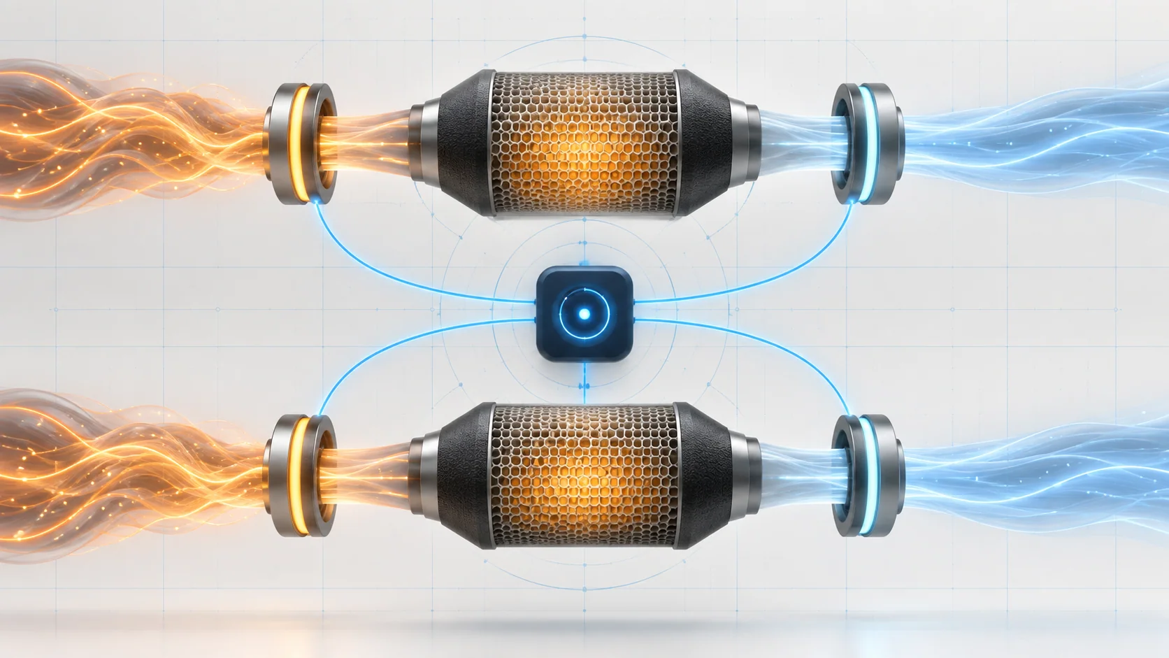
The 6.4-liter HEMI uses heated oxygen sensors before and after each catalytic converter so the powertrain control module (PCM) can evaluate combustion feedback and catalyst performance. The upstream sensors respond directly to the exhaust leaving the engine; the downstream sensors report what remains after the catalyst. Heater faults, sensor-circuit faults, exhaust leaks, engine problems, and catalyst damage can all change this evidence. A catalyst-efficiency DTC is therefore a test result, not an automatic instruction to replace the converter.
Applicability and service-information boundary
This overview applies to the 2019-2025 Ram 2500HD 6.4 HEMI Gas configuration. Authorized vehicle records confirm a Ram 2500 Truck 4WD application with the 6.4-liter V8 in every model year from 2019 through 2025, and Ram model-year material identifies the engine family as the 6.4L HEMI V8.
The detailed operating and diagnostic information reviewed for this overview comes from the exact 2025 application. Sensor construction, wiring, calibration, monitor conditions, scan-tool functions, exhaust hardware, and service procedures can change by year and equipment. Use current service information for the exact truck whenever a test requires a value, connector, command, drive cycle, or removal procedure.
What the system is trying to determine
The system answers two related questions: does the exhaust-sensor information make sense, and is each catalytic converter storing and processing oxygen as expected?
Each exhaust bank has an upstream sensor before the catalyst and a downstream sensor after it. The upstream signal represents the changing oxygen content leaving the cylinders and is part of the PCM's air-fuel feedback. The downstream signal is exposed to exhaust that has passed through the catalyst. When the catalyst is functioning and the engine is under a valid monitoring condition, the downstream pattern should be more stable than the upstream pattern.
The PCM does not judge the catalyst from one instant of voltage. It first needs believable sensor and heater operation, then compares upstream and downstream activity over a calibrated monitoring period. If the downstream activity becomes too similar to the upstream activity, the PCM can interpret that as reduced catalyst oxygen-storage performance. The exact calculation and pass/fail boundary are calibration details, not a universal field specification.
Why the sensor heaters matter
An oxygen sensor needs sufficient temperature to produce useful, repeatable information. An internal heater brings the sensing element into its operating range quickly and helps maintain readiness when exhaust heat alone is not enough. The PCM commands and monitors the heater circuit rather than assuming that a warm exhaust guarantees a ready sensor.
That makes the heater an enabling part of the monitoring system. A heater-control or ground-circuit problem, excessive resistance, poor terminal contact, or a failed heater element can delay or distort sensor readiness. Diagnose an active heater or signal-circuit DTC before treating the same sensor's data as proof of catalyst condition.
How oxygen storage separates a healthy catalyst from an aging one
A three-way catalytic converter temporarily stores and releases oxygen while promoting reactions that reduce harmful exhaust gases. That storage action buffers the rapid rich-to-lean changes visible before the converter. A healthy catalyst therefore tends to produce a downstream signal with less rapid activity than the upstream signal during a valid monitor.
As a catalyst ages, becomes contaminated, overheats, breaks internally, or otherwise loses effective oxygen-storage capacity, more of the upstream exhaust pattern can pass through. Downstream activity then begins to resemble upstream activity. This comparison is useful only if both sensors, their heaters and circuits, the exhaust path, and the engine's combustion are credible.
What the related DTCs tell you
| DTC | Diagnostic category | What it directs you to prove |
|---|---|---|
| P0138 | Downstream O2 signal high | Whether a genuinely rich exhaust condition, signal/return fault, heater interaction, terminal problem, sensor fault, or controller-side issue explains the high signal |
| P0141 | Bank 1 downstream O2 heater performance | Whether the heater element, control side, ground side, connector/terminal condition, or controller is preventing expected heater behavior |
| P0420 | Bank 1 catalyst efficiency | Whether credible Bank 1 sensor evidence still shows reduced catalyst oxygen-storage performance after leaks, engine conditions, sensor concerns, and physical damage are excluded |
| P0430 | Bank 2 catalyst efficiency | Whether the same catalyst-monitor categories explain the Bank 2 result, using the opposite bank as a useful comparison where appropriate |
P0138 and P0141 identify sensor signal or heater categories. P0420 and P0430 identify catalyst-monitor results. None of the four codes, by itself, identifies the failed part.
What the driver or technician may notice
- a malfunction indicator lamp with otherwise normal operation;
- increased fuel consumption, roughness, hesitation, or an exhaust odor when an underlying mixture or combustion problem is present;
- a catalyst-related rattle, restricted-power complaint, or heat discoloration when the converter is physically damaged;
- multiple O2-sensor, fuel-trim, misfire, or catalyst codes rather than one isolated DTC;
- a pending code or stored operating record even when the symptom cannot be reproduced in the bay;
- monitor readiness that remains incomplete after codes or battery power were cleared.
These are possible observations, not a symptom checklist that proves one repair. Preserve the original scan and stored operating conditions before clearing codes.
Common failure categories
Sensor signal, heater, power, ground, or terminal faults
A signal that is shorted, open, biased, or affected by high resistance can look rich, lean, slow, or implausible. A heater circuit that cannot carry the commanded current can keep the sensor from reaching a useful operating state. Corrosion, water intrusion, heat damage, poor terminal tension, and harness contact with hot or moving parts deserve the same attention as the sensor itself.
Test the exact circuit under an appropriate load and inspect terminal fit before replacing the sensor or PCM. An unloaded voltage check can pass through a connection that fails in operation. Do not apply battery voltage, use an unsuitable test light, or pierce sealed wiring unless the current service procedure explicitly allows the method.
A real mixture or combustion problem changes the exhaust
An injector, ignition, airflow, purge, fuel-pressure, engine-mechanical, or control problem can create exhaust that is genuinely rich, lean, or oxygen-heavy. Misfire adds oxygen to the exhaust while also sending unburned fuel and heat toward the catalyst. Oil consumption, coolant entry, or excessive fueling can contaminate or overheat sensors and converter material.
Resolve active misfire, mixture, injector, and relevant engine faults before making a catalyst verdict. Replacing a converter without correcting the cause can damage the replacement.
Exhaust leakage changes what a sensor sees
Air drawn through a leak can change the oxygen content near a sensor and make its signal unrepresentative. Leaks at joints, flanges, damaged tubing, sensor threads, or the converter boundary can also disturb the relationship the monitor expects. Even a leak that is quiet at idle may matter under the pressure and pulsation present during the original failure condition.
Inspect and test the exhaust path with a safe, suitable method. Repair leakage before evaluating catalyst efficiency.
Sensor aging, contamination, or replacement-history mismatch
A sensor can remain electrically connected yet respond slowly or carry a biased pattern. Contamination from oil, coolant, fuel, sealants, or outside chemicals can alter its behavior. Repair history matters because a new downstream sensor paired with an aged upstream sensor may change the comparison enough to expose a plausibility problem.
Compare both banks and sensor positions under the same operating condition. Use the applicable response or functional test rather than judging a sensor only from appearance or one voltage snapshot.
The catalytic converter is damaged or has lost capacity
A converter can lose efficiency through normal aging, contamination, severe overheating, impact damage, internal breakage, or prolonged exposure to a misfire or rich mixture. Look for dents, holes, leakage, rattling, internal breakup, or abnormal discoloration. A physically damaged converter still requires a root-cause check.
Replace a catalytic converter only after upstream causes and the evidence paths used by the monitor have been proven. The absence of visible damage does not prove efficiency, but the presence of P0420 or P0430 does not prove the converter either.
A practical system-first diagnostic strategy
1. Preserve the evidence and confirm applicability
Confirm the exact model, engine, exhaust configuration, calibration status, and current service information. Save the complete module scan, confirmed and pending DTCs, freeze-frame or failure-record data, monitor status, fuel trims, misfire information, and relevant upstream/downstream sensor data before clearing anything.
2. Establish code priority
Handle active O2 heater, signal, reference, power, ground, misfire, injector, fuel-trim, or engine-mechanical faults that can invalidate catalyst evidence. P0138 is not an instruction to replace the downstream sensor, and P0141 is not proof that the heater element itself has failed. Likewise, P0420 and P0430 should not outrank faults that make their input signals untrustworthy.
3. Inspect the complete exhaust and harness environment
With the system cool, inspect wiring routing, connectors, terminal locks, heat shielding, sensor installation, exhaust joints, impact damage, leakage evidence, converter condition, and areas disturbed by recent work. Check for signs of oil, coolant, or excess-fuel contamination. Correct an obvious root cause before running extended tests.
4. Prove heater and signal integrity
Use the exact procedure to command or observe heater operation, compare related sensors, and prove the heater element and circuit under load. Then evaluate whether the signal responds plausibly to real exhaust changes. Separate an actual rich condition from an electrically forced high signal. Leave controller replacement until sensor, wiring, connector, and terminal integrity have been isolated.
5. Compare banks and sensor positions
View upstream and downstream activity together and compare Bank 1 with Bank 2 under the same stable condition. Look for a pattern that follows one sensor, one bank, both banks, or an engine operating region. A graph is more useful than one instantaneous value, but the pattern must be judged only when the sensors are ready and the monitor conditions are appropriate.
6. Prove the engine and exhaust are not misleading the monitor
Test for exhaust leakage, active mixture control problems, misfire, oil or coolant consumption, excessive fueling, and other engine conditions supported by the scan evidence. Review recent sensor and converter replacement history. Correct these causes and re-evaluate the data before deciding that catalyst oxygen storage is low.
7. Evaluate the catalyst only with valid inputs
After the sensors, heaters, circuits, exhaust path, and engine condition are credible, use the manufacturer-specified catalyst test or monitor. Compare Bank 1 and Bank 2 when the exhaust configurations and operating conditions make that comparison valid. A converter decision belongs at the end of the path, not at the beginning.
8. Verify the complete repair
Reconnect every sensor and retainer, restore shields and harness routing, clear codes only when directed, and complete any required setup. Reproduce the stored operating region or perform the current verification routine. Confirm that the relevant monitor completes, sensor behavior remains plausible, and no pending or confirmed DTC returns. A cleared lamp with an incomplete monitor is not a verified repair.
Safety around oxygen sensors and catalysts
Exhaust manifolds, pipes, oxygen sensors, and catalytic converters can remain hot long after the engine is switched off. Allow the system to cool, wear appropriate eye and hand protection, and keep flammable material away. Support the truck at approved lifting points with equipment rated for its weight; never work beneath a vehicle supported only by a jack.
Running tests place the technician near fans, belts, hot exhaust, and moving driveline parts. Route leads and hoses securely and use exhaust extraction in an enclosed work area. Follow current precautions for sensor removal, seized threads, penetrating products, electrical probing, and converter handling.
Final takeaway
On the 2019-2025 Ram 2500HD 6.4 HEMI Gas, the oxygen sensors and catalytic converters form one evidence chain. Upstream sensors report the exhaust leaving the engine, downstream sensors report the exhaust after each catalyst, and heaters help make those signals available when the PCM expects them. The catalyst monitor can make a valid decision only when those signals, the exhaust path, and engine operation are credible.
Preserve the operating evidence, establish DTC priority, prove heater and signal circuits, inspect for leaks and contamination, compare both banks, and correct engine causes before making a converter decision. The linked STEP guides provide model-specific educational paths; current service information for the exact truck controls specifications, commands, connectors, removal procedures, and final verification.