
Mechanic Guides
Current Clamp Arrow Direction: Define Positive Before Reading Negative
Interpret a negative DC clamp reading using its physical arrow, zero and display settings. Includes a polarity record for shop handoffs.
Published · 4 min read
Quick answer
For a DC-sensitive clamp, the arrow defines a positive reference according to the tool instructions. A negative reading needs that reference, a valid zero and the display settings before it can support a direction-of-current conclusion.
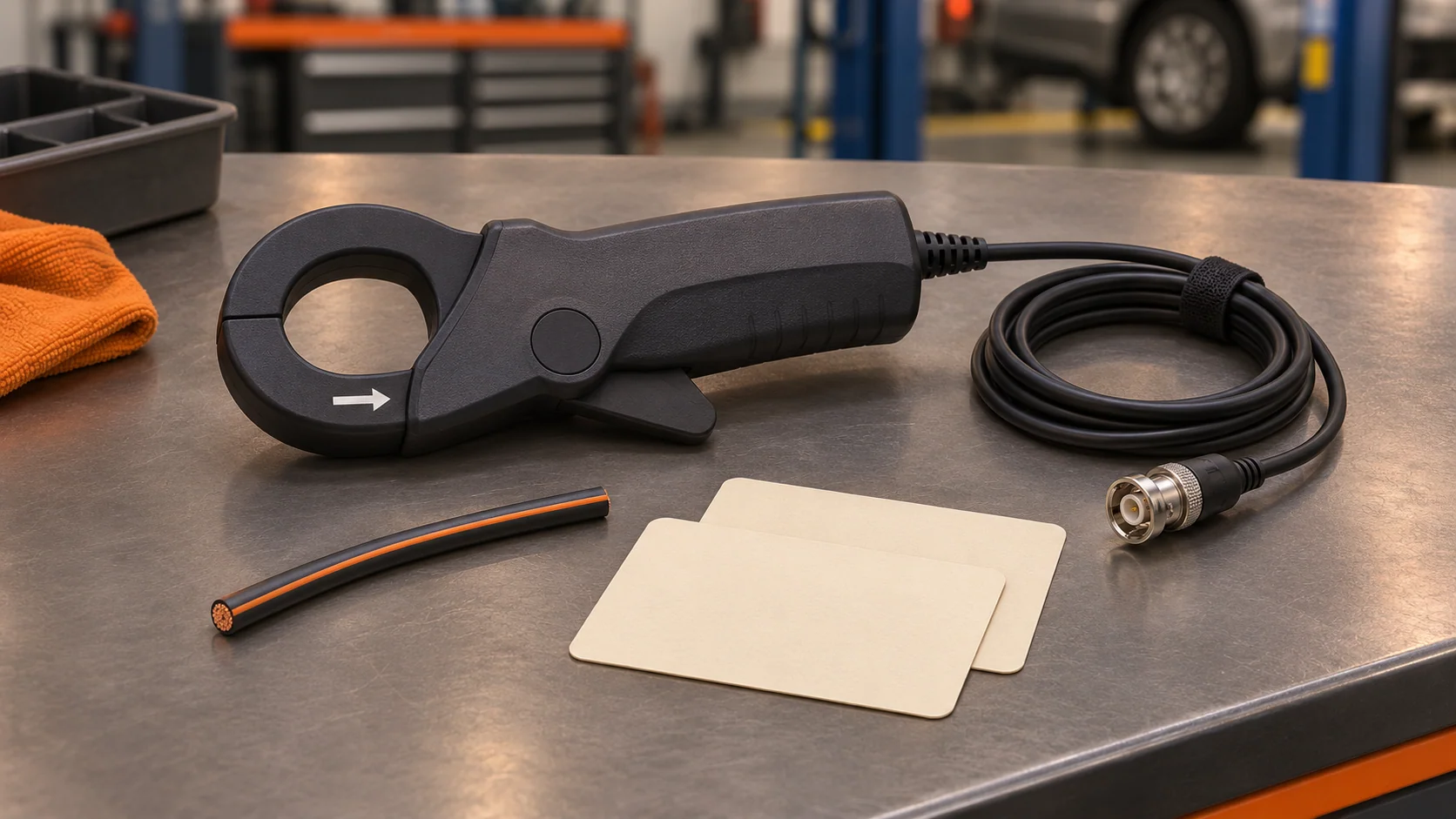
A technician saves a current trace below zero. The next person sees the minus sign, but the job record does not show which way the clamp faced. That missing detail leaves a basic question unanswered: negative relative to what? A useful capture needs a physical direction reference as well as a number.
Read the arrow on the actual clamp
Check the instructions for the exact probe or clamp meter. Pico's TA018 user guide describes the jaw arrow as the current-flow reference and says reversing the clamp inverts the displayed signal. Its range selection, output sensitivity and DC zero are separate setup requirements. An arrow from a photograph of a different clamp is not a substitute for identifying the one on the job.
Before recording, describe the arrow using two recognizable physical landmarks. For example, “arrow points from connector X toward the harness branch” is more repeatable than “clamp facing forward.” Identify the single conductor and measurement location. Use a setup photo when it can show those details clearly, while keeping customer identifiers out of shared material.
Keep orientation and vehicle behavior separate
Fluke's explanation of the clamp arrow uses a DC load example: reversing the clamp reverses the sign for the same current. It also explains why a scalar AC RMS reading can retain its magnitude when the clamp is reversed, even though the waveform polarity changes. Record the measured quantity; an AC RMS number is not a signed DC direction indicator.
Consider an illustrative, unchanged DC current that reads +2.40 A in one orientation and -2.40 A after the clamp is reversed, with the measurement setup otherwise valid. The changed reference explains that pair without requiring the vehicle current to reverse. These are invented teaching values, not a vehicle test or acceptance limit.
A sign change during a recording with the clamp untouched is a different observation. Preserve the capture and note what the vehicle was doing. Check the measurement setup before deciding whether the current changed direction. Do not relabel an unexplained negative reading as charging, discharge or component failure from its sign alone.
Check zero and the complete display path
A direction interpretation becomes weak when the indicated value is close to an unresolved offset. Follow the exact clamp's zero procedure and check whether its range, accuracy and readout can distinguish the current in question. The DC clamp zero guide covers that separate preparation task. Zeroing does not choose the physical positive direction.
For a scope probe, record the physical sensitivity setting and the selected software probe or conversion factor. Note any channel inversion, math operation or later sign change in an exported copy. Keep the original capture alongside a transformed view, with the transformation identified. If the display path cannot be reconstructed, label the sign interpretation unresolved and plan a repeatable measurement.
Purkeys' vehicle ammeter demonstration likewise calls attention to both the selected range and the arrow, including a negative indication from reversed placement. That practical check does not establish that every clamp can resolve a small key-off draw. Use the instrument specifications and applicable vehicle procedure for the actual test.
Give the next technician a polarity record
The downloadable record is an original handoff aid. Fill it in before reducing a capture to a pass/fail sentence:
- Instrument and probe identification; manual reference.
- Single conductor, location and a setup photo or sketch reference.
- Arrow points from which physical landmark toward which landmark.
- Measured quantity, range, sensitivity and displayed units.
- Zero-check conditions and result.
- Display inversion, scaling or math, including “none” when verified.
- Original file, signed reading and vehicle operating state.
- What the observation supports, what remains unresolved and the next check.
Keep this record with the diagnostic report. If multiple conductor passes are deliberately used in a suitable setup, document that separately using the multiple-turn clamp guide; the polarity reference still needs to be visible.
STEP is inviting shops into Early Access. Share how your team keeps measurement context and the next diagnostic check attached to a case.