
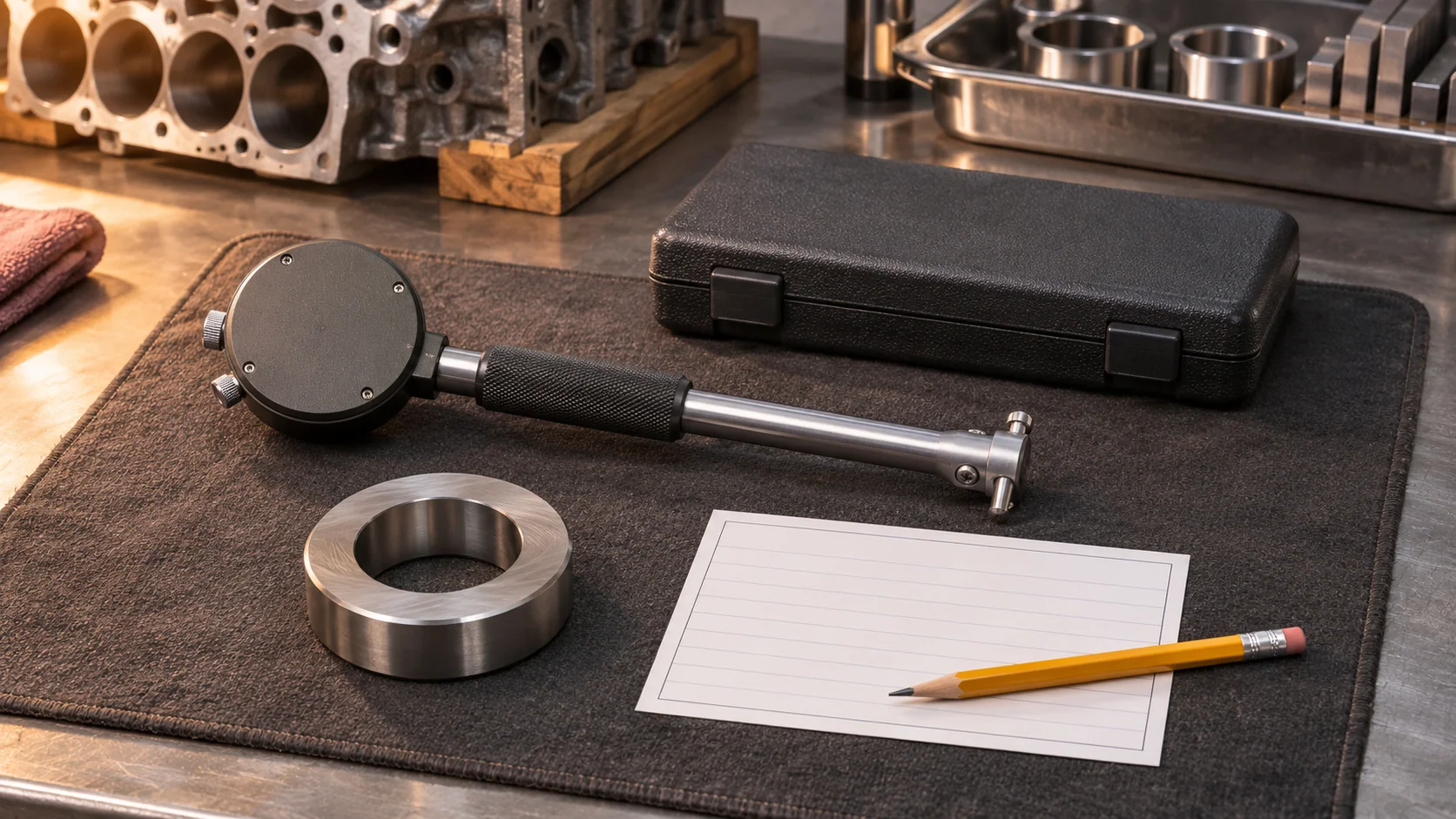
Start with the measurement you need
A bore-gauge reading can reach the repair order without the size used to set it. Another technician then sees “two divisions” and cannot reconstruct the measurement. Preserve the setup before collecting the readings.
For cylinder, housing or bearing work, retrieve the applicable service procedure first. It determines the required assembly condition, measurement locations, instrument and acceptance limits. This guide addresses reference setting and documentation. It supplies no engine dimensions, wear limits or permission to substitute a different measurement method.
Choose and identify the reference
Record the gauge model, indicator, units and graduation, plus the anvil or extension combination. Select a reference and setup suitable for that instrument and required measurement uncertainty. A setting ring, outside micrometer or dedicated setting fixture is not automatically interchangeable in every procedure.
Mitutoyo's Check Points booklet, printed page 6, describes cleaning the contact and anvil, securing the gauge and establishing zero before use. It illustrates an outside-micrometer setup and identifies a dedicated bore-gauge checker. Follow the actual model instructions for support and orientation rather than balancing the gauge between unsupported measuring faces.
Write down the reference's assigned dimension and units. Include its identifier and verification status under the shop's measurement-control procedure. Closing a micrometer to check its zero does not establish its accuracy at every size; a different instrument's zero check and calibration are also separate questions.
Establish a repeatable comparison point
Use this original shop checklist alongside the gauge manual:
- Confirm the correct measuring range and contact combination; inspect for damage, dirt and loose parts.
- Prepare and support the reference as its instructions require. Record the dimension before moving the bore gauge into position.
- Apply the specified indicator engagement or preload. Do not borrow a preload figure from a different model.
- Find the alignment and turning point described in the manual, then set the dial reference there.
- Remove and reintroduce the gauge to see whether you can reproduce the setting. Preserve those repeat observations before measuring the part.
“Rock it to the minimum” is too vague to serve as a universal instruction. The Haas dial bore gauge manual distinguishes alignment across a ring's diameter from movement along its axis; its specified zero-setting motion uses the maximum indicated value at the latter turning point. Geometry, motion and indicator convention belong together. Use your gauge's instructions to identify the correct point.
If the setting will not repeat within the requirement established for the job, pause and resolve the setup. Repeatedly rotating the bezel can conceal a shifting reference without correcting its cause.
Carry the reference into the result
Treat the result as a reference size plus a signed dimensional difference. Establish which direction means a larger bore from the instrument instructions and approved verification method. Pointer direction alone is an inadequate label for someone reading the record later.
For an arithmetic illustration only, a reference of 80.000 mm and a verified dimensional difference of +0.025 mm gives 80.025 mm. Those numbers are invented to explain the record format; they are not a vehicle specification, measured result or tolerance. Do not assign a positive sign merely because a needle moved clockwise.
For each required location, keep the depth or position, measurement orientation, reference size, signed difference and calculated dimension together. Do not infer the condition of an entire bore from one location. Compare the completed measurements with the applicable service limits and assembly instructions.
Close the measurement session
Return to the reference and record the closing observation before changing the setup. This is an editorial control step for the worksheet, not a claim that one universal check frequency applies to all gauges.
If that check calls the setup into question, retain the original readings and flag the affected measurement group for review. Document what was checked or changed and which measurements were repeated. Do not overwrite earlier values with a newly zeroed result.
The downloadable reference-and-reading record provides fields for that handoff. A Plastigauge clearance record concerns a different measurement process; agreement between two methods does not erase either method's preparation requirements.
Bring a reconstructable record to the case
STEP is accepting Early Access requests. Share how your shop needs to retain the measurement source, setup, observed result and next unresolved check. Keep the instrument record with the case so the next technician can understand what the number means.