What this code means
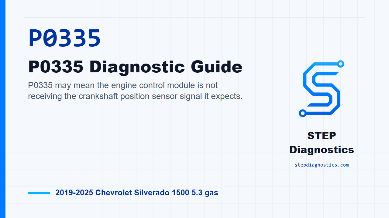
P0335 may mean the engine control module is not receiving the crankshaft position sensor signal it expects.
What the vehicle may do
- The vehicle may crank longer than normal.
- The engine may stumble or stall.
- The vehicle may have a no-start condition.
- The check engine light may be on.
Possible fault areas
- Possible crankshaft position sensor circuit issue.
- Possible low reference, reference feed, or signal circuit issue.
- Possible wiring, terminal, or connector concern.
- Possible sensor installation, reluctor, timing-drive, or synchronization concern.
Diagnostic path
Open: what P0335 is telling us
On this Silverado, P0335 points to a crankshaft position sensor signal problem. In plain terms, the engine control module may not be seeing the crank signal it expects. The truck may crank longer, stumble, stall, or have a no-start depending on when the signal drops out. The broad fault areas can include the crank sensor circuit, the low reference, the reference feed, the signal wire, connector or terminal issues, and sometimes a synchronization or mechanical relationship issue around the reluctor and timing components. Start with the basic system checks, follow a structured diagnostic approach, and if other codes are present, check what they mean first so you do not chase the crank sensor circuit out of order.
Monitor gate and set logic
Before testing the circuit, understand what the controller is looking for. This monitor runs only after the right operating gates are met. For P0335, one gate uses MAF Sensor = Greater than 3 g/s, along with a received camshaft position signal and the required crank or running state. For the related performance side, one gate uses Engine Speed = Greater than 450 RPM, so treat that as context when reproducing a sync concern, not as a separate parts list. The failure formula is simple: the controller sees no crankshaft position sensor signal. Depending on the operating condition, it can set after no signal for greater than 4 s, greater than 1 s, or over the required engine-revolution check. Use those gates to reproduce the operating conditions later, but do not turn the running-condition list into a parts list.
Circuit and system verification
Begin verification with the ignition on and the vehicle in Service Mode. First, make sure the reference-related codes called out in this path are not set. If they are set, handle that code path first. If they are not set, run the engine. With the engine running, check whether the related crank performance or synchronization code is present. If it is present, move into circuit and system testing. If it is not present, stay in verification.
Use the scan data before touching the circuit
Now watch the scan tool. The Crankshaft Position Active Counter should increment. If it does not increment, go to circuit and system testing. If it does increment, keep going. Next, monitor the Crankshaft Position Resync Counter. It should stay at 0 Counts, and the engine should not stumble or stall while you wiggle the harness and connectors at the crankshaft position sensor and at the engine control module. If the resync counter goes greater than 0 counts during that harness check, repair the wiring, terminals, or electrical connectors as necessary. If it stays at 0 counts, reproduce the operating conditions for the code, or the captured conditions from the vehicle data, and confirm the code does not reset. If the code comes back, go to circuit and system testing. If it does not reset, this verification path is all OK.
Power down, disconnect, and check low reference
For circuit testing, turn the ignition and vehicle systems off. Give the modules time to power down; it may take up to 2 min before a ground or low-reference continuity test is accurate. Disconnect the crankshaft position sensor connector. Then test the low reference circuit at terminal 2/B to ground. You are looking for less than 10 Ω. If it is 10 Ω or greater, disconnect the engine control module connector and check the low reference circuit end to end, from terminal 2/B at the component harness to the matching control module harness side. That circuit should be less than 2 Ω. If it is 2 Ω or greater, repair the open or high resistance in the circuit. If it is less than 2 Ω, the next step is engine control module replacement. If the original low reference test was less than 10 Ω, continue testing.
Check the 5 V reference
Turn the ignition on with the vehicle in Service Mode and check the 5 V reference at terminal 3/C to ground. The expected range is 4.8 to 5.2 V. If it is less than 4.8 V, turn the vehicle off, disconnect the engine control module connector, and test the 5 V reference circuit at the component harness to ground for infinite resistance. If it is less than infinite resistance, repair the short to ground. If it is infinite resistance, check that same 5 V reference circuit end to end. It should be less than 2 Ω. If it is 2 Ω or greater, repair the open or high resistance. If it is less than 2 Ω, the next step is engine control module replacement.
Handle a high 5 V reference result
If the 5 V reference is greater than 5.2 V, turn the vehicle off and disconnect the engine control module connector. Then turn the ignition back on in Service Mode and test the 5 V reference circuit at terminal 3/C on the component harness to ground. It should be less than 1 V. If it is 1 V or greater, repair the short to voltage on the circuit. If it is less than 1 V, the next step is engine control module replacement. If the 5 V reference is within 4.8 to 5.2 V, move on to the signal circuit check.
Simulate the crank signal response
With the 5 V reference in range, rapidly tap a 3 A fused jumper wire between the signal circuit terminal 1/A and ground. Watch the Crankshaft Position Active Counter. It should increment. This is a controlled way to see whether the module can recognize activity on the signal circuit without guessing at the sensor first.
If the active counter does not increment
If the active counter does not increment during the signal simulation, turn the vehicle off, disconnect the engine control module connector, then turn the ignition back on in Service Mode. Test the signal circuit at terminal 1/A on the component harness to ground. It should be less than 1 V. If it is 1 V or greater, repair the short to voltage. If it is less than 1 V, turn the vehicle off and test the signal circuit to ground for infinite resistance. If it is less than infinite resistance, repair the short to ground. If it is infinite resistance, test the signal circuit end to end from terminal 1/A at the component harness to the control module harness side. It should be less than 2 Ω. If it is 2 Ω or greater, repair the open or high resistance. If it is less than 2 Ω, the next step is engine control module replacement.
If the active counter increments
If the active counter increments, the signal path can be recognized by the module. At that point, check whether the related crank performance or synchronization code is present. If it is not present, test or replace the crankshaft position sensor. If that related performance condition is present, inspect for mechanical, installation, and contamination issues before condemning the sensor. In practical terms, check sensor installation, reluctor ring play, debris between the sensor and reluctor, air gap, loose or damaged parts, sprocket wear or damage, dirty or contaminated engine oil, and timing-drive or tensioner wear or damage. If one of those conditions exists, repair or replace as necessary. If none of those conditions exists, test or replace the crankshaft position sensor.
Verify the repair
After the repair, keep verification separate from the fault testing. Recheck the system, reproduce the operating conditions or the captured conditions that originally set the code, and confirm the code stays gone. If a return point in the diagnostic path is unclear, pause, recheck the earlier diagnostic path, and avoid guessing.
Takeaway
The main point with P0335 is to prove the crank signal circuit in order: low reference, reference feed, signal response, then sensor or mechanical synchronization concerns only after the circuit results support that direction. For more diagnostic training, visit stepdiagnostics.com.
Final check
P0335 is often best approached by proving the circuit and scan-tool response before moving toward the sensor or mechanical synchronization checks.
For more guided automotive diagnostics, visit STEP Diagnostics.