Fuel delivery is more than a pump producing one pressure. On the Chevrolet Silverado 1500 5.3 gas engine, the supply stage, high-pressure stage, pressure information and injector commands must work together. A pressure-control fault, a questionable sensor signal and an injector-circuit fault can cause overlapping symptoms while requiring different tests.
This overview covers the 2019–2025 Chevrolet Silverado 1500 5.3 gas profile. Sources at the first and last years support the functional explanation, not identical pump designs, sensor encoding, engine equipment, calibrations or procedures for every build. Confirm the exact engine and configuration. The applicable service information controls pressure limits, circuit identification, test equipment, commands, depressurization, replacement requirements and repair verification.
How fuel reaches the cylinders
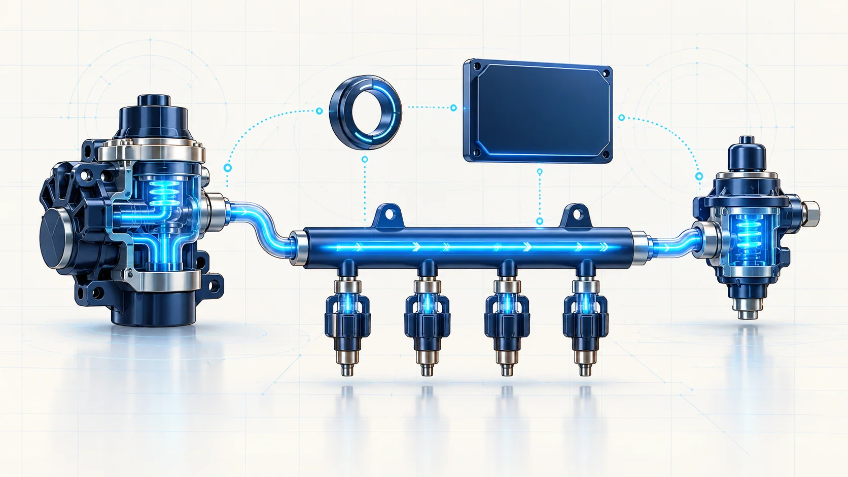
The system uses an electronically managed, on-demand returnless design. An electric pump in the tank supplies fuel to the engine's high-pressure pump. That pump supplies a variable-pressure rail, and the direct injectors deliver fuel into the combustion chambers. These are separate functional stages; a scan value from one stage cannot automatically establish the condition of the other.
On the endpoint engines examined, the high-pressure pump is mechanically driven by the camshaft and incorporates an electrically controlled valve. The controller varies pressure according to engine operating needs by controlling delivery during pump operation. The mechanical drive and the electrical control path therefore both matter when actual pressure does not follow the expected behavior.
The rail distributes pressurized fuel to the injectors. The engine controller coordinates pressure, injection timing and injection duration. Opening an injector electrically and delivering the correct amount of fuel are related but different outcomes: a functioning circuit does not prove correct flow, and a flow concern does not automatically identify an electrical fault.
Feedback must be trustworthy
Pressure information helps the controller judge whether fuel control is behaving as expected. A scan-tool pressure value is the controller's interpretation of a signal, not an independent mechanical measurement. Supply/reference faults, signal problems, connections or sensor condition can make a displayed value misleading.
Do not assume that every pressure sensor uses a simple analog voltage-to-pressure relationship. Signal encoding, available data channels and diagnostic comparisons depend on the application. Two named scan parameters do not by themselves prove that two separate physical sensors are fitted. Use the exact circuit description and scan-data definitions before choosing a measurement or interpreting a disagreement.
For the same reason, a fixed extreme or implausible displayed value should not immediately be treated as actual rail pressure. Establish the signal's validity and the applicable fault behavior first. Never use an ordinary low-pressure gauge or an improvised connection on the high-pressure side to settle that question.
Three STEP guides and their boundaries
| Guide | Diagnostic focus | What the code alone does not establish |
|---|---|---|
| P0089 — fuel-pressure regulator performance | Whether high-pressure control and the observed response behave as expected under the applicable conditions. | That the high-pressure pump is the failed part. |
| P0191 — fuel-rail pressure sensor performance | The plausibility and stability of pressure information and the supporting sensor circuits. | That the displayed value is a proven physical pressure, or that the sensor must be replaced. |
| P0201 — injector control circuit | The electrical command/response concern for the relevant cylinder's injector path. | That the injector has a mechanical flow fault, or that replacement is justified without isolation tests. |
The linked guides provide more detailed diagnostic paths. Their exact pressures, sensor comparisons, connector assignments and test connections remain subject to the vehicle's applicable procedure. This overview does not turn those details into universal specifications across the model-year range.
Failure categories and possible symptoms
The truck may have extended cranking, difficult starting, hesitation, loss of power, rough running, misfire or stalling. An intermittent fault may leave only stored evidence when the truck reaches the workshop. None of those symptoms identifies a pump, sensor or injector by itself.
- Supply and fuel condition: inadequate delivery, restriction, leakage or contaminated fuel can affect the high-pressure system's ability to meet demand.
- High-pressure generation and control: pump condition, its control valve, electrical operation or mechanical drive can affect pressure response. A pump electrical check does not establish the complete hydraulic condition.
- Measurement faults: reference, low-reference, signal, connector or sensor problems can corrupt pressure information. Intermittent spikes or dropouts may require a controlled connection/harness investigation.
- Injector electrical faults: opens, high resistance, shorts or connection problems can disrupt command response. Direct-injection drivers are not ordinary low-energy test circuits.
- Injector hydraulic faults: leakage or restricted delivery can affect combustion or rail behavior even when basic electrical checks pass. Use the prescribed injector tests rather than treating one resistance reading as a flow test.
A practical diagnostic strategy
- Preserve the evidence and identify the system. Record all codes, their status and available event data before clearing them. Note when the complaint occurs, fuel quality/history, recent work and the exact engine equipment. Identify which pressure stage and which scan parameter each observation represents.
- Check for a safety stop. A fuel odor, visible wetness or suspected pressurized leak requires safe isolation and the applicable inspection procedure before running tests. Severe rough running, stalling or loss of power may make road reproduction unsafe.
- Resolve related faults in the prescribed order. Position/timing, sensor-supply, pump-control and other supporting faults can alter the correct diagnostic branch. Do not interpret pressure response through an input already known to be unreliable.
- Validate the measurement. Check relevant data for plausibility, agreement where the procedure requires it and stability. Inspect connections and wiring safely. A sensor-circuit concern needs its own evidence before interpreting the reading as a hydraulic failure.
- Separate supply, pressure control and injector operation. Follow the applicable pressure-response tests with rated equipment and approved commands. A normal idle observation does not prove operation under the complaint conditions. For an injector-circuit code, isolate the electrical path before making a component decision; use separate hydraulic or contribution tests when directed.
- Investigate the supported cause. The repair may involve fuel condition, a connection, wiring, a sensor, delivery restriction/leakage, pump control or drive, or an injector. Mechanical inspection and control-module replacement belong only where the full diagnostic evidence directs them, not as shortcuts from a code name.
- Verify the original failure mode. Restore all connections, follow required installation/setup steps, confirm there are no leaks using the approved method, and recheck pressure behavior, relevant circuit status and codes under suitable conditions. Clearing a code or obtaining one normal reading is not a completed repair verification.
Safety comes before a pressure test
Direct-injection fuel pressure can remain hazardous after shutdown. Follow the exact pressure-relief procedure and verify the required safe state before opening any connection. Do not loosen a line to see whether pressure is present, search for a pressurized leak with a hand, or substitute an unrated gauge, hose or fitting. Suspected injection injury requires urgent medical attention even if the skin wound looks small.
Control ignition sources, provide ventilation and use the required eye and body protection. Keep fuel away from hot exhaust components. Follow replacement and handling requirements for pipes, seals, fittings and injectors; this article does not establish which parts may be reused.
Injector drivers can operate above battery voltage. Use correctly rated instruments and the exact test method. Do not apply battery power to an injector, improvise jumpers or probe a driver with an unsuitable test lamp. Allow the specified power-down time before resistance or continuity checks.
For running tests, use exhaust extraction and keep personnel and leads clear of moving parts. Do not reproduce a full-load maneuver simply because a generic guide mentions one. Use a safe approved test environment and the exact procedure; during road verification, record data safely or use another technician rather than watching a scan tool while driving.
The diagnostic goal is a complete evidence chain: trustworthy measurement, a valid operating test, separation of electrical and hydraulic causes, a supported repair and safe repeat verification.