What this code means
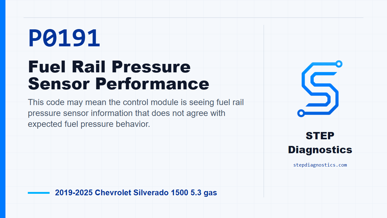
This code may mean the control module is seeing fuel rail pressure sensor information that does not agree with expected fuel pressure behavior.
What the vehicle may do
- The warning light may turn on.
- The vehicle may have hesitation, rough running, hard starting, or reduced performance.
- The concern may be intermittent if the issue is in wiring, terminals, or a connector.
Possible fault areas
- Possible fuel pressure and temperature sensor issue.
- Possible sensor connector, wiring, or terminal issue.
- Possible reference supply, low reference, or signal circuit issue.
- Possible control module involvement after circuit checks support it.
Diagnostic path
Opening context
On this Silverado, P0191 is a fuel rail pressure sensor performance code. In plain terms, the control module may be seeing fuel pressure information that does not agree with what it expects. The truck may turn the warning light on, may have driveability complaints, or may act differently under certain fuel demand conditions. Broad possible fault areas can include the fuel pressure and temperature sensor, the sensor connector, wiring and terminals, the reference supply, the low reference, the signal circuit, or possible control module involvement after the circuit checks support it. If other codes are present, especially codes around reference voltage, signal circuits, low reference, fuel pressure, or related sensor inputs, check what they mean first. This same diagnostic path can also catch faults that did not set their own separate code.
How P0191 is judged
For P0191, treat the running conditions as monitor gates. The check runs with fuel rail pressure in a steady state, ignition on, and then continuously after the conditions are met. The code is looking at the difference between Fuel Rail Pressure Sensor 1 and Fuel Rail Pressure Sensor 2. If that difference is greater than a predefined value for greater than 2.6 s, P0191 can set. As a scan-data reference at engine idle, the listed normal range is 3.9 to 4.2 MPa (565 to 609 PSI), and the listed fault value is 655.4 MPa (95058 PSI).
Start with verification before circuit testing
Start with the basic system checks, then follow a structured diagnostic approach instead of jumping straight to a part. With the ignition on and the vehicle in Service Mode, look at Fuel Rail Pressure Sensor 1 on the scan tool. It should read 0.6 to 655.4 MPa (87 to 95058 PSI). If it is outside that range, go to circuit and system testing. If it is in range, compare Fuel Rail Pressure Sensor 1 and Fuel Rail Pressure Sensor 2. They should be within 2 MPa (290 PSI) of each other. If they are not, go to circuit and system testing. If they match within that tolerance, keep watching Fuel Rail Pressure Sensor 1 while you wiggle the harness and connectors at the B310 Fuel Pressure/Temperature Sensor and at the K20 Engine Control Module. The value should not spike or drop out. If it does, repair the wiring, terminals, or electrical connectors as needed. If the signal stays stable, reproduce the operating conditions, or the captured conditions from the scan data, and confirm P0191 does not reset. If it resets, continue into circuit and system testing. If it does not reset, the check is OK at that time.
Low reference circuit testing
For circuit and system testing, turn the ignition, vehicle, and all vehicle systems off, then disconnect the B310 Fuel Pressure/Temperature Sensor connector. Before doing ground or low reference continuity checks, remember that it may take up to 2 min for all vehicle systems to power down enough for an accurate test. Test for less than 10 Ω between low reference circuit terminal 1 and ground. If the reading is 10 Ω or greater, disconnect connector X2 at the K20 Engine Control Module and test for less than 2 Ω between low reference circuit terminal 1 at the component harness and terminal 3 at the control module harness. If that continuity test is 2 Ω or greater, repair the open or high resistance in the circuit. If it is less than 2 Ω, replace the K20 Engine Control Module. If the first low reference to ground test was less than 10 Ω, move on to the 5 V reference check.
5 V reference circuit testing
With the low reference passing, turn the ignition on and put the vehicle in Service Mode. Test for 4.8 to 5.2 V between 5 V reference circuit terminal 3 and low reference circuit terminal 1. If it is less than 4.8 V, turn the ignition and vehicle off, disconnect connector X2 at the K20 Engine Control Module, and test for infinite resistance between 5 V reference circuit terminal 3 at the component harness and ground. If it is less than infinite resistance, repair the short to ground. If it is infinite resistance, test for less than 2 Ω between 5 V reference circuit terminal 3 at the component harness and terminal 39 at the control module harness. If that is 2 Ω or greater, repair the open or high resistance. If it is less than 2 Ω, replace the K20 Engine Control Module. If the 5 V reference is greater than 5.2 V, turn the ignition and vehicle off, disconnect connector X2 at the K20 Engine Control Module, turn the ignition on with the vehicle in Service Mode, and test for less than 1 V between 5 V reference circuit terminal 3 at the component harness and ground. If it is 1 V or greater, repair the short to voltage. If it is less than 1 V, replace the K20 Engine Control Module. If the 5 V reference is between 4.8 and 5.2 V, continue to the signal circuit test.
Signal circuit testing
Next, test for 4.8 to 5.2 V between signal circuit terminal 2 and low reference circuit terminal 1. If the signal circuit voltage is less than 4.8 V, turn the ignition and vehicle off, disconnect connector X3 at the K20 Engine Control Module, and test for infinite resistance between signal circuit terminal 2 at the component harness and ground. If it is less than infinite resistance, repair the short to ground. If it is infinite resistance, test for less than 2 Ω between signal circuit terminal 2 at the component harness and terminal 63 at the control module harness. If that is 2 Ω or greater, repair the open or high resistance. If it is less than 2 Ω, replace the K20 Engine Control Module. If the signal circuit voltage is greater than 5.2 V, turn the ignition and vehicle off, disconnect connector X3 at the K20 Engine Control Module, turn the ignition on with the vehicle in Service Mode, and test for less than 1 V between signal circuit terminal 2 at the component harness and ground. If it is 1 V or greater, repair the short to voltage. If it is less than 1 V, replace the K20 Engine Control Module. If the signal circuit voltage is between 4.8 and 5.2 V, test or replace the B310 Fuel Pressure/Temperature Sensor.
Component check for the B310 sensor
For the B310 Fuel Pressure/Temperature Sensor component check, connect a 3 A fused jumper wire between 5 V reference terminal 3 and 5 V. Then connect a jumper wire between low reference terminal 1 and ground. Test for 2.5 to 4.0 V between signal terminal 2 and low reference terminal 1. If the voltage is not between 2.5 and 4.0 V, replace the B310 Fuel Pressure/Temperature Sensor. If it is between 2.5 and 4.0 V, that component check is OK.
Verification and takeaway
After the repair, verify the repair and confirm the code stays gone. The clean way through P0191 is to separate verification from circuit testing: confirm the scan data first, check for sensor disagreement and dropouts, then prove the low reference, reference supply, signal circuit, and sensor before condemning a module or sensor. For more diagnostic training, visit stepdiagnostics.com.
Final check
This code is often best handled by confirming the scan data first, then proving the sensor circuits and component response in order.
For more guided automotive diagnostics, visit STEP Diagnostics.