A misfire is a loss of consistent combustion contribution, not the name of a failed part. On the Chevrolet Silverado 1500 5.3 gas engine, ignition must work with fuel delivery, air handling and mechanical cylinder condition. The engine control module uses rotation information to recognize uneven contribution, while separate electrical diagnostics evaluate ignition-coil circuits.
This overview covers the 2019–2025 Chevrolet Silverado 1500 5.3 gas profile. Sources for the first and last years support the conceptual explanation; they do not establish identical engine equipment, cylinder-deactivation strategies, wiring, calibrations or service procedures throughout the range. Confirm the exact engine and build. The applicable service information controls cylinder identification, circuit connections, test conditions, specifications, learning and repair verification.
What the ignition system does
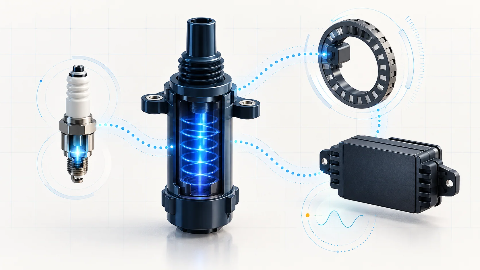
The ignition system supplies a timed, high-energy spark to ignite the compressed air-fuel charge. The controller uses crankshaft and camshaft position information to coordinate spark sequence and timing. Each ignition coil needs its electrical supply, ground and control paths to work correctly; a good command cannot produce a reliable spark through a damaged secondary path.
At a conceptual level, current builds a magnetic field in the coil's primary winding. Interrupting that current creates the secondary voltage needed for the spark. The controller and coil electronics coordinate this process. A plug, its associated lead or boot, the coil and its electrical connections therefore belong to one energy-delivery chain, but they are not interchangeable diagnoses.
An electrical circuit check and a spark-output check answer different questions. Neither by itself proves that a cylinder has adequate fuel, compression or valve operation under the complaint conditions.
How the controller recognizes a misfire
Combustion changes crankshaft acceleration. The misfire monitor looks for rotation-speed variations consistent with a weak or missing combustion event, using camshaft information to associate events with cylinders. Scan-tool counters help identify a pattern and the conditions in which it appears; they do not identify the failed component.
The controller must also distinguish combustion-related changes from other influences on rotation. Rough-road information and the applicable monitor conditions matter. A vibration felt in the cab is not automatically proof of engine misfire, and a quiet counter outside the relevant test window does not close an intermittent complaint.
Crankshaft variation learning supplies a reference correction for small crankshaft and sensor-related tolerances. That supports misfire detection. It does not restore compression, repair an injector or cure a weak spark. A successful learn and a successful combustion repair are separate outcomes.
Three guides, three diagnostic questions
| STEP guide | What it helps establish | What it does not prove |
|---|---|---|
| P0300 — engine misfire detected | The combustion-pattern diagnosis: counters, cylinder contribution and separation of ignition, fuel, air and mechanical causes. | That a coil, plug or injector has already failed. |
| P0351 — ignition-coil control circuit | An electrical diagnosis involving the relevant coil-control path, its connections and supporting circuits. | That replacing the coil is justified without circuit evidence. |
| P0315 — crankshaft variation not learned | A learn-status concern and the need to establish the correct prerequisites and completed routine. | That a crankshaft sensor or control module should be replaced solely from the code name. |
The linked guides contain more detailed paths. Confirm that their exact code family, engine equipment and procedure match the vehicle before using any threshold or test connection. This overview does not generalize a brake-pedal learn, retry count, jumper method or module-replacement decision across the model-year range.
Failure categories and symptoms
The truck may run roughly, hesitate, shake or lose power. A malfunction light may be steady or, during a catalyst-damaging misfire, flash. Some learn-status or intermittent circuit concerns may be present without a persistent rough idle.
- Ignition energy delivery: worn or damaged plugs, contamination, tracking, a damaged lead or boot, coil condition or the supporting electrical path can reduce spark reliability.
- Electrical control and connections: supply, ground, reference, control-circuit or terminal faults can interrupt operation. A movement-sensitive connection may behave normally during a static inspection.
- Fuel and air: injector operation, delivery or fuel-quality problems, mixture faults and air leaks can produce uneven combustion without a failed ignition part.
- Mechanical cylinder condition: compression, valve operation and other engine faults can create a weak cylinder. Abnormal engine noise changes the diagnostic priority.
- Detection and prerequisites: an incomplete variation learn, related position-signal faults or an invalid test opportunity can complicate interpretation. These are not permission to ignore genuine combustion symptoms.
Cylinder-deactivation equipment varies. Where fitted, investigate its involvement only through the exact engine's diagnostic path; a counter pattern alone does not prove a sticking lifter or justify engine disassembly.
A practical diagnostic strategy
- Preserve the complaint evidence. Record all faults, their status and available event data before clearing anything. Note temperature, load, fuel history, recent work and whether the symptom is continuous or intermittent.
- Check for a reason to stop. Severe rough running, a flashing light or abnormal engine noise calls for a safe response, not repeated attempts to force the monitor. Follow the mechanical path when noise or other evidence directs it.
- Resolve related faults and prerequisites. Establish supply condition, position-signal concerns and the required learn status using the applicable procedure. Do not repeatedly run a learn to conceal an unresolved engine problem.
- Establish the pattern. Compare cylinder counters under safe, relevant conditions. Use an approved cylinder-contribution or power-balance test when directed. A weak contribution narrows the location, not the cause.
- Separate the branches. Follow the electrical path for a coil-circuit concern. For a combustion concern, use appropriate spark, fuel and mechanical tests rather than replacing a collection of parts. A controlled component substitution is evidence only when the exact procedure allows it and the fault moves in a meaningful, repeatable way.
- Repair the supported cause. The repair may involve a connection, wiring, an ignition component, fuel/air condition, mechanical defect or a required setup operation. Control-module replacement is a conclusion requiring its own complete evidence, not an early shortcut.
- Verify the original failure mode. Restore connections and removed components, complete required setup, and recheck counters, relevant circuit statuses and codes under appropriate conditions. An extinguished light or a completed learn alone is not proof of a repaired misfire. Follow applicable catalyst-performance verification after a damaging misfire.
Safety and verification boundaries
Ignition secondary voltage can injure. Switch the vehicle off before disconnecting components as directed, allow the specified power-down time, and use suitable rated equipment and the correct spark-testing method. Do not pull a lead by hand while the engine is running or improvise circuit jumpers from this illustration.
Keep hands, leads and clothing clear of belts, fans and hot exhaust components. Use exhaust extraction for running tests. Fuel diagnosis can involve hazardous pressure: follow the exact depressurization and test procedure, control ignition sources and do not open a pressurized fuel connection casually.
Learning and actuator routines can change engine operation. Follow every vehicle-specific scan-tool prompt and safety prerequisite; this article is not an instruction to accelerate an unloaded engine or perform a universal relearn. During road verification, record data safely or use another technician; do not watch a scan tool while driving.
If the light flashes with severe rough running, reduce load and stop safely. Arrange diagnosis or recovery if continued operation is unsafe. The goal is a trustworthy chain from complaint evidence to a proven cause, a targeted repair and a successful repeat check—not merely a cleared code.