Start by separating delivery, pressure feedback, and injection
The 2020–2025 Chevrolet Silverado 2500 6.6L Diesel needs a clean fuel supply, controlled rail pressure, believable sensor feedback, and correctly timed injector operation. A fault in any one of these paths can affect starting or engine performance, but the paths are not interchangeable. A low-pressure code does not automatically prove a failed high-pressure pump, and an injector circuit code does not prove a leaking injector.
This is an educational overview of the diesel vehicle profile. Exact service evidence was inspected for 2020 and 2025 4WD configurations, with supporting 2022 system-description context. The model-year range is not a claim that every connector, calibration, optional tank arrangement, or service procedure is identical. Use current service information for the VIN, build configuration, and applicable early/late procedure before selecting test points, limits, commands, or repairs. Gasoline Silverado fuel systems are outside this overview.
What the system does
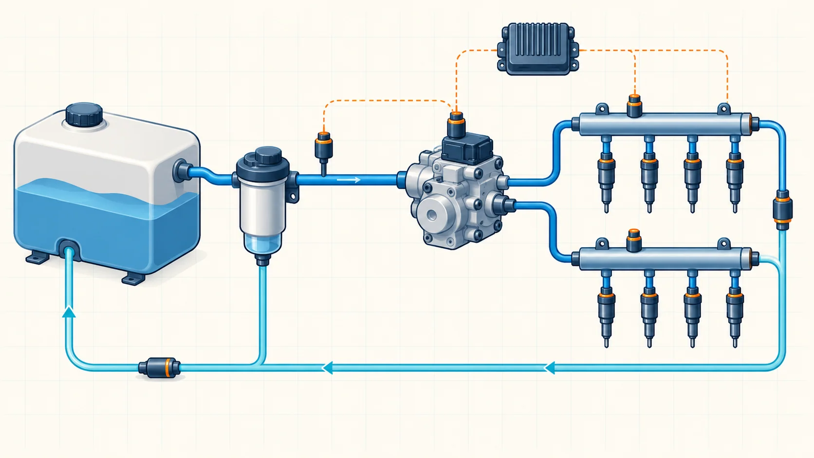
The low-pressure side transfers fuel from the tank through filtration to the mechanically driven high-pressure pump. The high-pressure side supplies the rails and injectors. Electronic control coordinates pump delivery, pressure regulation, and injector pulses so that the engine receives fuel at the required pressure and time.
Fuel also cools and lubricates fuel-system components. Contamination is therefore more than a filter-maintenance issue: water, gasoline, or other unsuitable material can affect operation and damage components. Fuel quality must be part of a pressure diagnosis, especially after refueling or a contamination complaint.
How the main functions work together
Supply and filtration
A brushless tank pump is controlled through the fuel-pump control module and engine controller. Fuel travels through the feed path and filter assembly before reaching the high-pressure pump. The filter-related assembly incorporates filtration, water separation, heating, and fuel-temperature information in the inspected configurations.
Supply pressure is monitored separately from rail pressure. A restricted filter or feed path, a supply-pump/control problem, or damaged plumbing can leave the high-pressure pump without adequate fuel. That is why checking the low-pressure side comes before condemning the high-pressure pump.
Optional auxiliary-tank and transfer arrangements must be identified on the actual vehicle. Do not assume that a component shown for an optional configuration is fitted to every Silverado in this profile.
High-pressure generation and regulation
The mechanical pump supplies the rails, which distribute pressurized fuel to the injectors. Two electronically controlled pressure-regulator functions manage fuel delivery from the high-pressure pump and fuel returning from the rail. Their operating roles depend on conditions and calibration; a simplified diagram cannot replace the vehicle's service description.
The controller compares desired rail pressure with measured rail pressure. A sustained disagreement can be associated with supply shortage, pressure-control problems, leakage, restriction, contaminated fuel, or unreliable pressure information. The comparison narrows the diagnostic question; it does not identify one failed part by itself.
Pressure and temperature feedback
In the inspected diesel system, the rail-pressure sensor provides two pressure signals that the controller checks for agreement. That is a different question from whether actual rail pressure follows the controller's target. Two signals can disagree because of the sensor, reference or low-reference paths, signal circuits, terminals, or connections.
Fuel-temperature feedback helps control operation under changing conditions. A circuit-high fault can produce an implausibly cold-looking scan value; it is not proof that the fuel is genuinely cold. Confirm the applicable sensor and module path before testing because optional configurations can change the diagnostic branch.
Injector operation and return flow
The controller energizes solenoid injectors to deliver fuel directly into the cylinders. Injector electrical control and injector hydraulic behavior are separate evidence paths. An electrical fault may disrupt commanded operation; an internal leakage or restriction concern requires the applicable hydraulic or cylinder-performance tests.
Unused fuel returns through the return system and cooler to the tank. Return flow is part of pressure management, not simply an irrelevant drain path. Its routing and test connections remain configuration-specific.
Failure categories and possible symptoms
- Supply restriction or inadequate low-side delivery can accompany hard starting, reduced power, stalling, or a no-start. Inspect the supply path and fuel condition before drawing a high-pressure conclusion.
- Regulation, high-side leakage, or injector hydraulic faults can affect pressure tracking and engine operation. Follow the directed procedure rather than improvising an injector-return test.
- Sensor or circuit faults can make scan information misleading. The vehicle may show a warning light with few symptoms, or it may have drivability concerns depending on the failed input and control response.
- Injector electrical faults can accompany rough running or reduced performance. Connector and wiring faults remain possibilities alongside the injector and controller.
- Contamination or cold-weather fuel restriction can affect delivery. The repair scope depends on the contaminant and the applicable service information; replacing only a filter is not a universal remedy.
These are possible associations, not proof of cause or a promise that every affected truck will show the same symptom.
Where the STEP DTC guides fit
| Diagnostic guide | Main question | What the code does not prove |
|---|---|---|
| P0087 — Fuel Rail Pressure Too Low | Is the monitored rail-pressure behavior failing, and is low-side supply adequate? | That the high-pressure pump alone is faulty |
| P0191 — Fuel Rail Pressure Sensor Performance | Are the rail-pressure signals plausible, responsive, and consistent with the applicable procedure? | That a measured discrepancy is necessarily a hydraulic failure |
| P0201 — Cylinder 1 Injector Control Circuit | Does the cylinder 1 electrical control path behave as commanded? | That the injector leaks internally or must be replaced |
The linked guides help identify a diagnostic category. Their displayed year range does not make exact connector assignments or numerical tests universal. Early/late injector procedures can differ; confirm the correct branch against current vehicle-specific service information before electrical probing.
A practical diagnostic strategy
1. Preserve the complaint and failure evidence
Record when the symptom occurs, recent refueling or service, fuel level, stored and pending codes, and freeze-frame or failure-record data before clearing anything. Identify the exact engine, options, and build applicability. Starting, idle, cold operation, and loaded acceleration may expose different problems.
2. Address related electrical faults first
Look for pump-module, pressure-sensor, regulator-circuit, or injector-group faults that change the prescribed diagnostic order. Verify relevant power, ground, reference, low-reference, and signal paths using the correct procedure. A pressure number is weak evidence when the circuit producing it is already suspect.
3. Separate low-side supply from rail pressure
Identify each scan parameter before interpreting it: supply pressure, desired rail pressure, measured rail pressure, and redundant rail-pressure channels answer different questions. Use the vehicle's specified operating conditions and limits. Check supply delivery and the filter/feed path before progressing into high-pressure diagnosis.
4. Check data plausibility before pressure-control conclusions
For a sensor-performance complaint, compare the applicable pressure signals and their response, then investigate wiring or connector intermittents as directed. For a temperature complaint, ask whether the value fits operating conditions and whether a circuit fault could explain it. Do not use an implausible signal as proof of actual pressure or temperature.
5. Follow the selected hydraulic or electrical branch
For a verified pressure-control complaint, the OEM path may direct regulator-response checks, fuel-quality inspection, leakage/restriction checks, or dedicated high-pressure and injector tests. Those tests require their own prerequisites and equipment. For an injector circuit complaint, isolate the electrical path and perform the applicable component test before making a replacement decision. Do not mix limits or terminal assignments from different procedure branches.
Repair categories and verification
Repairs can include restoring damaged wiring or terminals, correcting a verified supply restriction or leak, servicing filtration and water separation, replacing a proven failed sensor or regulator, or repairing an identified injector or pump fault. Contamination may require a wider repair than the first failed component. Use the applicable contamination procedure, service parts, cleanliness rules, and any specified replacement or learning requirements.
After repair, verify correct assembly and the absence of leaks using the approved method. Check the relevant pressure or electrical behavior and reproduce the original failure conditions when safe. Confirm that the applicable monitor completes without the fault returning and that the complaint is resolved. Clearing a code or seeing a normal idle reading alone is not complete verification.
Safety before testing
Common-rail diesel fuel can cause serious injection injury. Do not loosen high-pressure connections with the engine running or use a hand to locate a leak. Follow the vehicle-specific shutdown and pressure-release instructions before opening the system; do not assume ignition-off alone proves zero pressure. Use approved equipment and protective measures, control ignition sources, and keep opened fuel components clean.
Injector drivers use elevated electrical voltage. Do not substitute a conventional test lamp, direct battery feed, or improvised jumper for the specified test equipment and procedure. Allow the specified shutdown period before resistance testing and confirm the correct early/late connector information. If safe equipment or exact applicability is unavailable, stop the intrusive test.
Key takeaway
Diagnose this fuel system as coordinated supply, pressure control, feedback, and injection functions. First establish believable data and adequate supply; then let the appropriate electrical or hydraulic procedure identify the failed path. A DTC is a starting point for evidence, not a parts order.
Return to the 2020–2025 Chevrolet Silverado 2500 6.6L Diesel diagnostic library for related guides.