What this code means
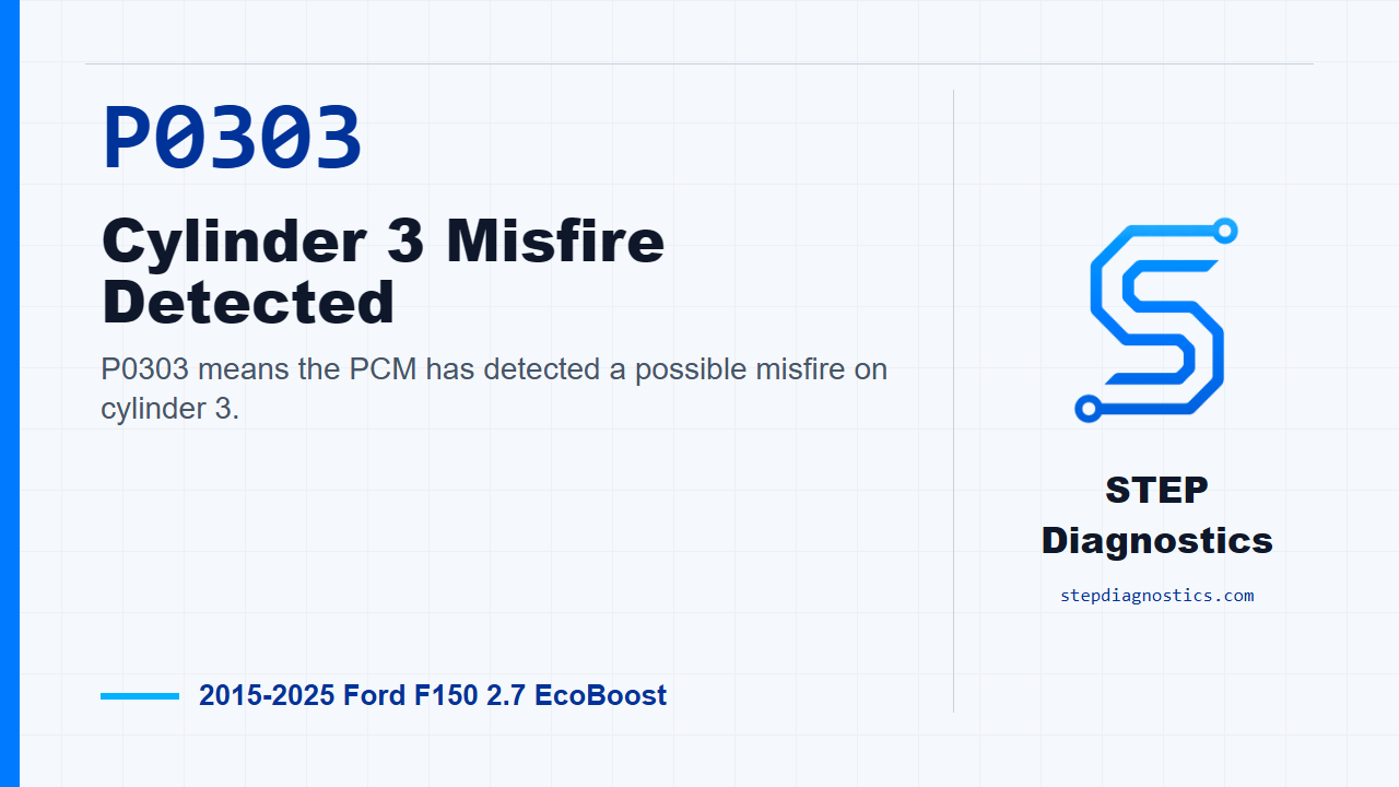
P0303 means the PCM has detected a possible misfire on cylinder 3.
What the vehicle may do
- The vehicle may idle rough.
- The vehicle may hesitate or shake under load.
- The check engine light may be on or flashing.
- Fuel economy may be reduced.
Possible fault areas
- Ignition faults may be involved.
- Fuel delivery or injector concerns can be possible.
- Vacuum leaks, EVAP hose issues, or EGR behavior may contribute.
- Base engine mechanical condition can be involved.
- Crank, cam, generator noise, or misfire monitor input concerns may affect detection.
Diagnostic path
What P0303 Means
On this 2.7 EcoBoost F-150, P0303 means the PCM has detected a misfire on cylinder 3. The truck may idle rough, hesitate, shake under load, or set the check engine light. Broadly, this kind of fault can come from ignition, fuel delivery, vacuum or EGR behavior, base engine condition, or a crank and cam signal issue. Work it in order, because the misfire monitor can also be fooled by mechanical noise, accessory drive issues, rough-road conditions, or high RPM light-load operation. Before clearing anything, save the captured operating data, because clearing PCM codes erases that information.
Start With Codes and Captured Data
Start by checking what codes are actually present. For this episode, we are following the path for P0303, and related misfire or system codes stay as context only. If the path points to a different priority code, handle that first. With P0303 active on this path, move into the misfire data review. Pull and record the PCM freeze frame PID values, then compare those values to the normal reference values. If something in that data is out of range, the diagnostic leaves this path for a separate test. If the values are not out of range, continue with mechanical confirmation.
Screen the Engine Before Chasing Parts
Next, run a relative compression test with the scan tool. If that test is not available, follow the passing branch and continue. If every cylinder passes, keep going. If a cylinder does not pass, confirm the mechanical side with cylinder leakage testing, and if needed, compression testing on the suspected cylinder. A misfire code is not automatically an ignition part failure, so do not skip this part of the workup.
Do Not Ignore Other Active Faults
After the mechanical screen, check for other non-misfire continuous memory codes. If other system codes are present, set P0303 aside for the moment and diagnose the next relevant code first. Then do the same with KOEO codes, and then KOER codes. If those checks do not produce another code to chase, continue with cylinder contribution testing.
Use Power Balance to Decide Whether to Enter Ignition Testing
Run the cylinder power balance test. If every cylinder is contributing correctly, move on to fuel injector flow. If the power balance shows a cylinder contribution problem, check the ignition system before going farther. On the ignition path, remember that a damaged ignition system can drive catalyst temperature up, so inspect nearby components around the catalyst and muffler for heat damage. Also, do not unplug a coil-on-plug unit with the engine running; that can damage the coil or the PCM.
Ignition Subtest Prechecks
When the ignition path is entered, check codes again in that ignition context. If a transport-mode related code is the issue, deactivate transport mode, clear the PCM codes, and repeat the self-test. Otherwise, continue with power balance. If all cylinders contribute correctly in that check, do a visual ignition inspection: make sure the coils are fully seated and connected, look over the harnesses and connectors for heat damage, broken areas, or loose connections, make sure the battery is in good condition, and turn accessories off. If a fault is found, repair it, clear the codes, and repeat the self-test. If not, continue testing the suspect coil circuit.
Check Power at the Suspect Coil
With the ignition off, disconnect the suspect coil connector, turn the ignition on, and check VPWR at the suspect coil connector pin for this engine family. The connector list covers the six 2.7 EcoBoost coils, but the cylinder-to-connector mapping is not identified in this diagnostic path, so do not guess the P0303 connector from list order. Confirm the correct connector by vehicle circuit identification before measuring. The voltage must be greater than 10.5 V. If it is, continue with the P0303 ignition branch. If it is not, repair the open circuit, clear the PCM codes, and repeat the self-test.
Follow the Cylinder-Specific Ignition Path
For a cylinder-specific misfire like P0303 on this 2.7 EcoBoost, the path goes to the spark check for the cylinder indicated by the code. There is also a bank-to-bank component swap path for confirmation. If you need that branch, pause, verify the correct cylinder and opposite-bank component pairing, and avoid guessing.
Test Spark Output Correctly
For the indicated cylinder spark check, turn the ignition off, remove the fuel pump fuse, disconnect the ignition coil from the spark plug, and connect an adjustable ignition spark tester or equivalent to the coil boot. Set the tester to 40 kV and crank the engine 3 times. Then set the gap to 25-28 kV, watch the tester, and crank the engine again. A correctly operating ignition system only has to spark in that 25-28 kV range. If spark is present there, move to spark plug inspection. If spark is not present on this engine, install a new coil or COP, clear the PCM codes, and repeat the self-test. If the ignition path instead calls for an all-cylinder spark check, the setup is the same: ignition off, fuel pump fuse removed, coils disconnected from the plugs, tester connected to the coil boot, gap first set to 40 kV, crank 3 times, then set to 25-28 kV and crank while watching the tester. If spark is present in all cylinders at 25-28 kV, continue to plug inspection. If it is not present on this engine, install a new coil or COP, clear the PCM codes, and repeat the self-test.
Inspect and Measure the Plug
The next component-inspection step in this shared ignition test is for the 3.3L Duratec-V6 only, where that path checks coil boots and spark plugs on the missing cylinders. Do not use that 3.3L-only step to make a decision on this 2.7 EcoBoost P0303. For this truck, continue to the spark plug inspection. If the coil can produce spark, pull the spark plug and inspect it for damage, wear, carbon tracking, deposits, and correct gap. If the plug condition is not acceptable, repair the plug issue, adjust the gap, or install a new spark plug as needed, then clear codes and repeat the self-test. If the plug looks OK, measure resistance from the center wire to the terminal. The expected range is between 2,000 ohms and 12,000 ohms at a room temperature of 25°C (77°F). If the resistance is outside that range, install a new spark plug, clear the PCM codes, and repeat the self-test. If it passes, continue back out of the ignition path.
Return to Fuel Checks After Ignition
If the ignition check does not confirm an ignition-related concern, return to the misfire path and continue with injector and fuel checks. Run the relative injector flow test. If the scan tool test is not available, follow the passing branch and continue. If the injectors are flowing correctly, move on. If one does not flow correctly, check for a loose connection or damaged or corroded pins, repair what is found, and then continue with the fuel system check.
Check Fuel, Vacuum, and EGR Behavior
Next, check the fuel system using the fuel-system diagnostic path. If that finds a fuel-related concern, repair it, clear the PCM codes, and repeat the self-test. If not, inspect the vacuum hoses for damage, deterioration, collapse, or restrictions feeding actuators or sensors. Also inspect EVAP lines and hoses for wrong connections or damage. Some vacuum leaks can be heard, but do not rely on sound alone. If no vacuum or EVAP concern is found on this engine, bring the engine to normal operating temperature and monitor the EGR-related PID at idle, then record it again with the ignition on and engine off. Compare those values to the normal references. If the EGR values are out of range, diagnose the EGR system. If they are in range, continue.
Recreate the Misfire Under Captured Conditions
Now disable the EGR system by turning the ignition off and disconnecting the EEGR assembly connector. Use the captured operating data and customer information to reproduce the conditions where the misfire showed up. The vehicle may need to be driven to reproduce the concern, and EGR-related codes may set while the connector is unplugged. If the misfire can be recreated with EGR disabled, continue to base engine checks. If it cannot be recreated, remove and inspect the EGR for contamination, unusual wear, carbon deposits, binding, or damage, repair as needed, clear the PCM codes, and repeat the self-test.
Check Base Engine and Air Handling Hardware
With the ignition off, evaluate base engine integrity. Check mechanically driven cooling fan operation where applicable, inspect the accessory drive area, confirm compression and leakage results, evaluate the valve train, inspect the PCV valve and tube for leaks, and run the applicable component checks. If the engine is equipped with IMRC, inspect the linkages for being disconnected or damaged, check for restriction, and make sure the plates can move fully open and fully closed. Engine temperature can affect these results, so keep that in mind when judging the test. If a concern is found, repair it, clear the PCM codes, and repeat the self-test. If no base engine concern is found, P0303 continues to the suspect injector disable check.
Command the Suspect Injector Off
Start the engine and use the PCM injector disable controls for the suspect cylinder. Command the suspect injector off. If the vehicle does not provide injector disable PIDs, follow the passing branch. If engine RPM changes when the suspect injector is disabled, continue to the later misfire monitor checks. If RPM does not change, inspect the suspect fuel injector connector and pins for damage, corrosion, or an incorrect connection. If the connector and pins are OK, install a new fuel injector, clear the PCM codes, and repeat the self-test.
Look for Signal and Noise Problems
From there, the path checks issues that can disturb the misfire monitor. Start the engine and monitor the cam synchronization PID. If there is a concern, verify that the cam sensor is installed correctly; if it is, continue. Then check the generator for excessive electrical noise. Listen with the engine running, turn the ignition off, disconnect the generator or regulator B+ connector, restart the engine, and see whether the noise stays the same. If the noise drops when the B+ connector is disconnected, diagnose the generator noise. If it stays constant, continue. Next, inspect the CKP harness for damaged wires or physical damage that could cause an intermittent CKP circuit short. Repair any harness issue found, clear the PCM codes, and repeat the self-test.
Finish the Misfire Monitor Inputs
Inspect the crankshaft pulse wheel for damaged teeth, wobble, or looseness. Inspect the crank pulley for wobble, and check the CKP sensor for damage. If anything is not OK, repair as necessary, confirm CKP sensor installation, reset KAM, and carry out the misfire monitor neutral profile correction with the scan tool. If those parts are OK, check for biased oxygen sensor data by monitoring the commanded and measured fuel control and trim PIDs, recording the values, and comparing anything that appears out of range. If a biased HO2S value may be the cause, inspect the HO2S, exhaust system, and HO2S mounting flanges for leaks or damage, repair as necessary, clear codes, and repeat the self-test. Finally, check recent repair history for rotating engine or accessory-drive components. If those components were recently replaced, carry out the misfire monitor neutral profile correction, then verify the repair by recreating the original conditions and watching cylinder misfire data in Mode 6. The misfire count must be below 10. If it is not, the path leaves to an intermittent or deeper diagnostic; pause there and avoid guessing.
Verify the Repair
Keep verification separate from testing. After any confirmed repair, clear the PCM codes, repeat the self-test, and reproduce the original operating conditions using the captured data and customer information. For P0303, the takeaway is simple: prove cylinder 3 is the problem, separate ignition, fuel, air, EGR, mechanical, and monitor-input causes in order, and do not skip the data that tells you when the misfire happened. For more diagnostic training, visit stepdiagnostics.com.
Final check
P0303 is best handled by confirming the cylinder-specific misfire, then separating ignition, fuel, air, EGR, mechanical, and monitor-input causes in order.
For more guided automotive diagnostics, visit STEP Diagnostics.