Quick answer
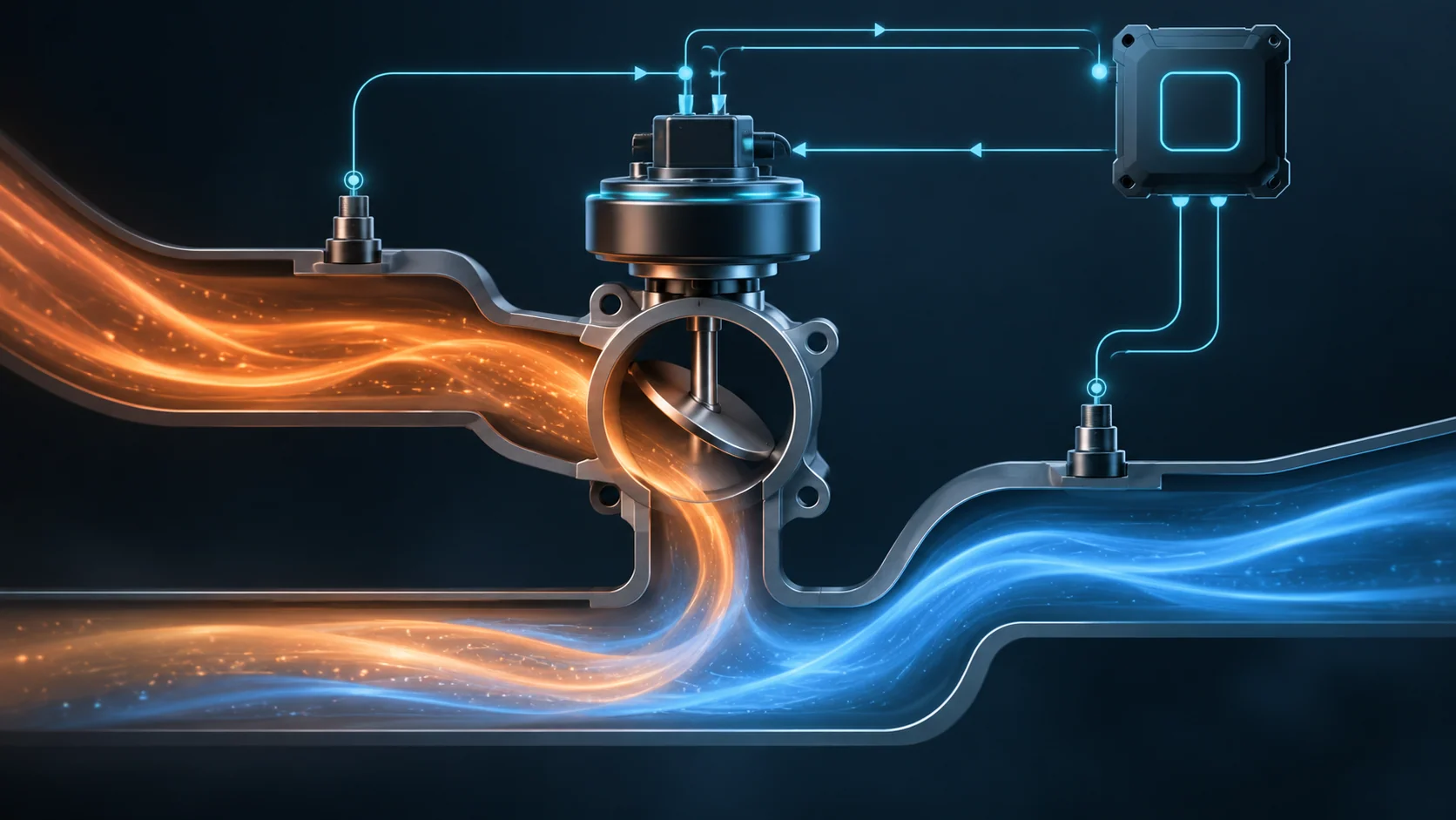
The exhaust gas recirculation (EGR) system meters exhaust back into the intake during selected operating conditions to reduce peak combustion temperature and nitrogen-oxide emissions. Depending on model year and configuration, the powertrain control module (PCM) may judge the system through valve-control circuits, valve-position feedback, and a pressure- or flow-response path. P0401, P0402, P0403, P0404, and P0405 identify different failures in that evidence chain; none of them proves that the EGR valve itself should be replaced.
Applicability and service-information boundary
This overview applies to the 2015–2025 Ford F-150 2.7L EcoBoost vehicle family represented by the linked STEP guides. Detailed operation and diagnostic evidence was verified on the exact 2025 Ford F-150 4WD 2.7L Turbo configuration. The exact 2015 Ford F-150 4WD 2.7L Turbo endpoint was also checked to establish the range boundary.
Code availability and EGR architecture are not uniform across the entire range. The verified 2025 configuration includes the P0401, P0402, P0403, P0404, and P0405 diagnostic families and separates electrical valve control from flow or pressure feedback. The verified 2015 endpoint lists an electric EGR control-circuit path for P0403, but it does not present the same P0401, P0402, P0404, and P0405 set. That difference is important: do not assume that every linked code, sensor, monitor, connector, or test applies to every truck in the year range.
Use current service information for the exact VIN, model year, engine, emissions package, calibration, and installed hardware whenever a test requires a connector view, circuit designation, specification, scan-tool command, monitor condition, component location, or service procedure.
What the EGR system does
Gasoline combustion can become very hot when cylinder filling, oxygen concentration, load, and ignition timing create a fast burn. The EGR system introduces a controlled amount of already-burned exhaust into the fresh charge. Because that exhaust contains less oxygen and can absorb heat, it moderates peak combustion temperature and helps reduce nitrogen-oxide formation.
The PCM does not command EGR continuously. Flow must be matched to engine speed, load, temperature, boost, and other operating conditions. Too little EGR can defeat the emissions strategy and contribute to combustion-temperature concerns. Too much EGR, or EGR at the wrong time, can dilute the charge enough to cause hesitation, surge, roughness, reduced torque, or stalling.
That is why EGR is a controlled system rather than a simple open-or-closed passage. The PCM must decide when flow is appropriate, command the valve, determine whether the valve responded, and decide whether the resulting gas flow is believable.
How the command and feedback paths work
The exact hardware changes across this vehicle family, but the diagnostic logic can be understood as three related questions:
- Did the PCM command the EGR valve electrically?
- Did the valve or its position feedback respond to that request?
- Did the exhaust-flow or pressure evidence change as expected?
On the verified 2015 application, the electric EGR valve uses a stepper-motor arrangement with multiple controlled windings. The PCM monitors those control paths for electrical faults. An open winding, damaged connector, wiring fault, or driver-side problem can prevent controlled movement even if the gas passage itself is clear.
On the verified 2025 application, the diagnostic information separates an electric valve-control side from a flow or pressure-feedback side. The PCM can therefore have a valid command but an implausible position or flow result. A restricted passage, contaminated pressure pickup, damaged feedback hose, leak, water or icing condition, carbon deposit, sticking mechanism, signal fault, or incorrect supporting input can break the expected relationship.
This separation prevents a common diagnostic mistake. Electrical movement does not prove useful exhaust flow, and a flow code does not prove that the valve actuator failed.
What the related DTCs tell you
| DTC | Diagnostic category | What it directs you to prove |
|---|---|---|
| P0401 | Insufficient EGR flow | Whether the commanded event produced the expected flow or pressure response, and whether restriction, carbon, leakage, feedback plumbing, sensor evidence, valve operation, or supporting engine data explains the weak response |
| P0402 | Excessive EGR flow | Whether gas is flowing when it should not, the valve is leaking or stuck, the feedback path is biased, or another condition makes flow appear greater than commanded |
| P0403 | EGR control-circuit fault | Whether the valve-control circuits, windings or actuator, connector, harness, power or control path, or PCM driver explain the electrical result |
| P0404 | EGR range/performance | Whether commanded and actual valve or flow evidence agree, and whether sticking, restriction, feedback, connection, wiring, or mechanical operation explains the disagreement |
| P0405 | EGR sensor circuit low | Whether a grounded, shorted, open, high-resistance, or otherwise biased signal path, connector, sensor, shared circuit, or controller-side condition is producing an implausibly low input |
The DTC tells you which part of the expected relationship failed. It does not select a replacement part. It may not even be available on the exact year being serviced, so confirm applicability before building the test plan.
What the driver or technician may notice
- a malfunction indicator lamp with no obvious drivability complaint;
- failure of an emissions inspection or monitor-readiness check;
- hesitation, surge, rough running, reduced power, or poor fuel economy;
- unstable idle or stalling if EGR flows when the engine cannot tolerate it;
- loss of response under load if commanded airflow and actual dilution do not agree;
- multiple EGR electrical, position, pressure, or flow codes rather than one isolated DTC;
- a fault that appears only during steady warm driving when the PCM enables the monitor;
- moisture, damaged feedback plumbing, soot, carbon, or a disturbed connector near the EGR path;
- a repeat code after valve replacement because the gas path, feedback path, wiring, setup, or root cause was not verified.
These are clues, not proof. Preserve the full vehicle scan, freeze-frame or failure-record data, pending codes, and recent repair history before clearing anything.
Common failure categories
Restricted exhaust path or carbon accumulation
Carbon can narrow an EGR passage, interfere with valve seating or movement, or contaminate a pressure pickup. The PCM may command EGR and see electrical movement while the expected flow response remains too small. Deposits can also create intermittent behavior as temperature changes.
Do not label every insufficient-flow code as a dirty valve. Prove which part of the path is restricted and use the cleaning or replacement method approved for the exact configuration. If deposits are excessive, consider the engine conditions that created them rather than treating cleaning as the entire repair.
Unwanted or excessive flow
A valve that does not seat, a mechanically stuck mechanism, a biased feedback signal, or an abnormal pressure relationship can make EGR flow appear excessive. If the system admits exhaust at idle or another inappropriate condition, the driver may notice roughness, hesitation, or stalling.
Separate actual unwanted gas flow from a false sensor indication. A scan value alone cannot prove that exhaust is moving through the passage.
Valve actuator or control-circuit faults
An electric EGR valve depends on intact control circuits, connector engagement, terminal fit, harness routing, and internal actuator continuity. The earlier verified configuration uses multiple motor-control paths, so one failed winding or circuit can compromise controlled movement. Later configurations still require proof of the command path before a mechanical conclusion is valid.
Inspect for corrosion, water intrusion, heat damage, chafing, backed-out terminals, poor retention, previous probing damage, and an actuator that binds. A command displayed by the scan tool proves only that the PCM requested an action, not that current reached the actuator or that the valve moved.
Position, pressure, or flow-feedback faults
The PCM may rely on valve-position information, differential-pressure or related flow evidence, and supporting engine data. A damaged hose, restricted pickup, water or icing condition, biased sensor, open or shorted circuit, poor ground or reference, or connection problem can make a healthy gas path look faulty.
Judge the whole evidence chain. If a supporting electrical DTC is active, resolve it before trusting the calculated flow conclusion.
Leakage and disturbed joints
Leaks at a valve, tube, gasket, feedback connection, or another EGR boundary can change the expected relationship between command and measured response. Escaping exhaust may leave soot and can expose nearby wiring or components to heat.
Inspect only after the system has cooled. Use the exact leak test and repair procedure for the installed hardware; visible soot is useful evidence but is not by itself a complete localization.
Calibration, learned values, and controller-side conditions
Software level, learned position, adaptive values, or a required post-repair routine may affect how the PCM judges EGR operation. A controller should remain at the end of the decision tree after installed hardware, circuits, connectors, feedback paths, calibration applicability, and required setup are proven.
A practical system-first diagnostic strategy
1. Confirm the exact configuration
Decode the vehicle and verify year, engine, emissions package, calibration, installed EGR hardware, and applicable DTC list. This step matters especially on the 2015–2025 range because the verified endpoints do not share the same code set or feedback architecture.
2. Preserve evidence and establish priority
Save all module codes, status, freeze-frame or failure records, monitor readiness, relevant temperatures, load, engine speed, EGR command and feedback data where available, and recent repair history. Diagnose active power, ground, reference, actuator-control, or feedback-circuit faults before trusting a flow-performance result.
3. Inspect the cold system
With exhaust components cool, inspect connectors, terminal locks, harness routing, heat shielding, valve and tube joints, feedback hoses or pickups where equipped, and recently disturbed areas. Look for soot, carbon, moisture, kinks, splits, corrosion, heat damage, loose retention, or previous test damage.
4. Compare command, response, and flow evidence
Use a capable scan tool and the current service procedure. Ask three separate questions:
- Did the command change under an allowed operating condition?
- Did valve-position or electrical response follow the command?
- Did the engine, pressure, or flow evidence respond plausibly?
Command without valve response points toward control circuits, actuator operation, connector integrity, binding, or feedback. Valve response without expected flow points toward restriction, leakage, a contaminated or damaged feedback path, or misleading supporting data. Flow when the command is closed points toward leakage, sticking, false feedback, or an incorrect operating conclusion.
5. Prove circuits without damaging terminals
Use the specified connector views, breakout method, meter loading, fused jumpers, and controller precautions for the exact truck. Do not borrow pin numbers, wire colors, resistance limits, or forced-signal steps from another year. Avoid piercing sealed wiring or spreading terminals unless the approved procedure expressly requires it.
An unloaded voltage reading may not prove that a circuit can carry the required current. Likewise, actuator continuity alone does not prove free mechanical movement or correct flow.
6. Isolate the gas and feedback paths
Once electrical control is credible, follow the applicable steps for restriction, leakage, sticking, feedback-hose condition, pressure pickup contamination, moisture or icing, and sensor plausibility. Do not force the valve, pressurize the system, or introduce chemicals outside the approved procedure.
7. Choose the repair category after localization
The supported repair may be a connector or harness repair, feedback-hose or pickup service, leak repair, approved passage cleaning, valve or sensor replacement, calibration update, required setup, or—only after complete isolation—controller repair or replacement. Match the repair to the failed section, not to the code name.
8. Complete setup and verify under the relevant condition
Restore all connectors, locks, harness supports, heat protection, and exhaust joints. Perform any required learned-value reset or component setup. Then reproduce the relevant monitor condition or follow the service-information verification routine. Confirm that command, position, and flow evidence agree and that no related pending or confirmed DTC returns.
Clearing the lamp is not a completed verification. Some EGR monitors need a particular warm, steady-state operating window before they can judge the system again.
Safety around the EGR system
EGR parts carry hot exhaust and can remain hot after shutdown. Allow sufficient cooling time, wear appropriate eye and hand protection, and keep tools, test leads, chemicals, and flammable material away from hot surfaces. Exhaust gas is hazardous; use effective ventilation and exhaust extraction whenever the engine must run indoors.
Running tests place the technician near fans, belts, turbocharger and exhaust heat, and potentially moving driveline components. Secure leads and tools, place the transmission in the specified state, apply the parking brake, and follow the current procedure before commanding an actuator or raising engine speed. Do not disconnect hot pressurized plumbing or use unapproved cleaners, compressed air, or electrical jumpers.
Final takeaway
EGR diagnosis on the 2015–2025 Ford F-150 2.7L EcoBoost is an evidence-chain problem. The PCM issues an electrical command, the valve or feedback system reports a result, and flow or pressure evidence shows whether exhaust actually moved as intended. P0401, P0402, P0403, P0404, and P0405 describe different breaks in that chain, and the exact set does not apply uniformly across every model year.
Start with exact configuration, preserve the operating evidence, prioritize electrical faults, compare command with position and flow response, and localize restriction, leakage, feedback, actuator, or circuit faults before choosing a repair. The linked STEP guides provide the code-specific educational path; current service information for the exact VIN controls connector details, values, commands, procedures, and final verification.