What the electronic throttle and idle-control system does
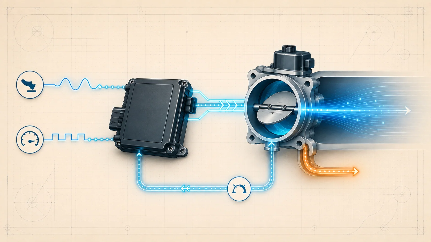
The electronic throttle system controls engine airflow without a mechanical cable between the accelerator pedal and throttle plate. The powertrain control module (PCM) interprets driver demand and current engine conditions, commands the electric throttle actuator, monitors throttle position, and coordinates fuel, ignition, transmission, and other torque-related functions.
At idle, the same throttle body meters the air needed to keep the engine running at the requested speed. The PCM changes throttle angle as electrical loads, temperature, transmission state, learned airflow, and other operating conditions change. Unwanted air entering around the commanded throttle path can therefore create both an idle-speed problem and an airflow-versus-throttle rationality problem.
Private service-information targets confirm 2015 and 2025 F-150 4WD 2.7L turbo endpoints, while the linked STEP guides use the 2015-2025 educational grouping. The detailed system description reviewed for this overview is from the exact 2025 application. Confirm the VIN, engine application, calibration, throttle-body design, connector information, relearn requirements, and current service procedure before testing or replacing anything. Exact values and procedures can differ within the grouped range.
An electronic-throttle or idle DTC identifies a behavior the PCM could not verify. It does not automatically prove that the throttle body or PCM has failed. Intake leakage, PCV flow, crankcase sealing, a restricted air path, a biased supporting input, wiring damage, learned values, or a mechanical throttle concern can all change the evidence.
The main functional sections
- Accelerator-pedal input: Pedal sensing represents driver demand. The PCM validates that demand before requesting engine torque; the pedal does not directly move the throttle plate.
- PCM torque strategy: The PCM decides how much torque to request and coordinates throttle angle with fuel, ignition, transmission operation, and protective limits.
- Electronic throttle body: An electric motor moves the throttle plate. A return spring provides a default mechanical position if normal electronic control is unavailable.
- Throttle-position feedback: Internal sensing reports actual plate position so the PCM can compare the response with its command and detect implausible operation.
- Idle airflow control: The PCM uses small throttle-angle changes to maintain requested idle speed as conditions and loads change. Learned idle-air correction helps compensate for gradual variation.
- Air path, PCV, and crankcase sealing: All air reaching the cylinders affects engine speed and calculated load. Air bypassing the intended throttle path can make actual behavior disagree with the PCM's model.
- Supporting engine inputs: Temperature, airflow, pressure, engine speed, transmission state, electrical-load, and other valid inputs help determine the appropriate throttle and idle command.
How throttle command and idle feedback work together
The driver presses the accelerator pedal, the PCM interprets that request, and the throttle actuator moves the plate to support the requested torque. The PCM watches throttle-position feedback and engine response while coordinating other actuators. The plate does not simply mirror pedal movement; torque management can change throttle angle during shifts, idle operation, or protective strategies.
At idle, the PCM has a target engine speed and meters airflow through the electronic throttle body to maintain it. If an accessory or operating load changes, the controller can adjust throttle angle and other outputs. It can also learn correction values that account for normal variation over time.
The PCM expects airflow, load, throttle position, and engine response to agree. A leak in the intake or PCV path can admit air the controller did not command. A sticking, binding, or damaged plate can change actual airflow. A sensor or circuit fault can make a normal mechanical condition look implausible. This is why diagnosis must separate commanded control, actual throttle movement, unintended airflow, and the credibility of supporting inputs.
What the related DTCs are telling you
| DTC | Diagnostic category | What it directs you to prove |
|---|---|---|
| P0068 | Airflow/load relationship does not agree with throttle position | Whether intake, vacuum, PCV, crankcase sealing, throttle movement, supporting sensor evidence, or an electrical concern caused the rationality failure |
| P0507 | Idle speed higher than commanded | Whether unmetered air, intake or PCV leakage, restriction, throttle airflow, learned correction, or another input prevents the PCM from controlling idle as expected |
P0068 is not a throttle-body replacement instruction. P0507 is not proof that the throttle motor is holding the plate open. Both codes require the technician to prove whether the PCM is commanding the wrong result, receiving misleading evidence, or losing control because air is entering through another path.
What the driver or technician may notice
Possible observations include:
- a malfunction indicator lamp with little other complaint;
- idle speed that is higher than expected, hangs, flares, or settles slowly;
- rough idle, hesitation, or reduced power depending on the failure;
- a wrench or powertrain warning when the system enters a limited-control strategy;
- throttle response that is reduced or deliberately limited by fail-safe operation;
- a concern that changes with temperature, accessory load, gear selection, harness movement, or recent intake work;
- companion airflow, pressure, temperature, pedal, throttle-position, PCV, or power-supply codes.
Symptoms help reproduce the concern but do not identify the failed part. A high idle can result from air bypassing a correctly commanded throttle plate, while reduced response can be a protective reaction to another detected fault.
Safety before throttle and intake testing
An electronic throttle plate can move whenever the system is powered or commanded. Keep fingers, tools, cleaning material, and test leads out of the throttle bore while the ignition is on or the actuator can operate. Do not force the plate or apply battery voltage directly to the actuator or PCM-controlled circuits unless the exact service procedure explicitly requires a specified method.
Allow hot engine and turbocharger-area components to cool before inspecting nearby hoses or wiring. Work in a ventilated area, secure loose clothing, and keep clear of belts, fans, and other moving components when the engine must run. Use eye protection and follow the applicable service procedure for any intake or throttle-body work.
Use terminal-safe probes and the correct wiring diagram. Do not guess at pins, pierce insulation unnecessarily, or use an unfused jumper. Disconnect power only when the applicable procedure requires it, and understand that learned idle or throttle values may require a specified reset or relearn afterward.
Common failure categories
1. Unmetered intake or vacuum air
A cracked tube, loose clamp, damaged gasket, disconnected hose, or other leak can admit air outside the intended path. The engine may idle high even though the PCM is trying to close the throttle, and airflow/load calculations may no longer agree with throttle position. Inspect the complete path from the air cleaner through the throttle body and intake manifold as applicable.
2. PCV or crankcase-sealing problem
The crankcase ventilation system is part of the engine's airflow path. Incorrect PCV flow, damaged hoses or seals, an oil cap or dipstick sealing problem, or a related crankcase-pressure input concern can alter measured and calculated airflow. P0068 may route into this branch because the throttle relationship can be disturbed without a failed throttle body.
3. Intake restriction or throttle-bore condition
A restricted filter or duct changes available airflow. Damage or binding at the throttle bore can affect the small airflow changes used at idle, and a plate that does not return correctly can create command-versus-response evidence. Inspect before replacing; use only the approved service method.
4. Throttle actuator or position-feedback fault
The motor, internal position sensing, connector, power/control path, or wiring can prevent the plate from reaching or reporting the commanded position. Compare commanded and actual behavior with the directed scan-tool and circuit tests. Do not energize the actuator with a generic jumper.
5. Supporting-input or reference-circuit fault
The PCM's torque and idle decisions depend on credible speed, load, airflow, pressure, temperature, pedal, and power-supply information. A biased input or shared reference/return problem can make the throttle system appear faulty. Diagnose direct circuit codes and common electrical faults before a rationality or idle-performance code.
6. Learned-value or previous-repair mismatch
Idle correction values adapt to gradual system variation. Clearing DTCs, resetting keep-alive memory, replacing an idle-control component, or completing another repair that affects idle can reset or invalidate previously learned correction. Preserve diagnostic evidence first, then perform only the reset or relearn required by current service information.
7. PCM or calibration concern
PCM failure is a last branch, not a first guess. Prove powers, grounds, reference and return circuits, inputs, actuator wiring, terminal condition, mechanical airflow, and current software or configuration requirements before a module decision.
A practical diagnostic sequence
1. Preserve the complete evidence
Scan all modules before clearing codes. Save freeze-frame or snapshot data, code status, requested and actual idle information, throttle command and position, engine speed, load, airflow, pressure, temperature, pedal data, and the operating condition in which the fault set. Record recent intake, PCV, throttle, battery, calibration, or wiring work.
2. Establish code priority
Address power, ground, reference-voltage, pedal, throttle-position, actuator-circuit, airflow-sensor, and communication faults before relying on a P0068 correlation or P0507 idle-performance result. A rationality code may be the downstream effect of a more direct fault.
3. Confirm the complaint and fail-safe state
Verify whether the actual idle is high and whether throttle response is normal, limited, or intermittent. Do not interpret a deliberately reduced response as proof of a mechanical throttle failure. Reproduce the original temperature, load, and transmission state only when it is safe.
4. Inspect the complete air path
With the ignition off, inspect the air cleaner, ducts, clamps, throttle bore, vacuum hoses, intake sealing, PCV plumbing, crankcase sealing points, and related connectors. Check for restriction, loose installation, contamination, chafing, heat damage, corrosion, and poor terminal fit. Repair an obvious fault and verify it before moving deeper.
5. Compare command, feedback, and engine response
Use the directed scan data for the exact application. Determine whether the PCM is requesting a change, whether the throttle-position feedback follows, and whether engine speed and calculated load respond logically. A high idle with a nearly closed commanded throttle points the diagnosis toward unintended airflow rather than automatically toward the actuator.
6. Test circuits safely
Use the current wiring diagram, terminal-safe probes, and isolated continuity, short, load, or voltage-drop tests as directed. Move the harness while watching relevant data when the concern is intermittent. Verify shared supplies and returns before replacing a sensor, throttle body, or PCM.
7. Confirm the component or system cause
Use the applicable vacuum, PCV, crankcase-pressure, throttle, or idle-trim test only after the earlier branch supports it. Do not substitute a generic value, force the throttle plate, or declare a part failed from one PID snapshot. If the evidence points to mechanical engine sealing or another subsystem, diagnose that cause first.
8. Verify the repair
After the confirmed repair, clear codes or learned values only when the procedure requires it. Perform the specified idle or throttle relearn if applicable, repeat the relevant self-test, and reproduce the original conditions safely. Confirm requested and actual idle agree, throttle response is normal, no intake leak remains, and neither the original nor a new supporting-input code returns.
Repair direction by confirmed cause
- Repair intake, vacuum, PCV, or crankcase-sealing leaks before replacing the throttle body.
- Correct restrictions, damaged ducts, loose clamps, or a confirmed throttle-bore concern when inspection and the directed test support it.
- Repair power, ground, reference, return, signal, connector, terminal, or harness faults before replacing an actuator or sensor.
- Replace the electronic throttle body only when mechanical movement, position feedback, actuator response, or the directed test proves it faulty.
- Correct biased supporting inputs or shared-circuit faults that make airflow, load, and throttle evidence disagree.
- Perform only the specified memory reset, calibration, or relearn after the related repair.
- Do not replace the PCM until its powers, grounds, circuits, inputs, outputs, connector condition, and current diagnostic path support that conclusion.
Final takeaway
Electronic throttle and idle control are one coordinated system. The PCM interprets driver demand, commands throttle angle, watches position and engine response, and adapts idle airflow while other engine and transmission functions share the torque request. Diagnose the relationship, not just the named part. Separate unintended air from actuator response, supporting-input credibility, and learned-value effects before replacing the throttle body or PCM. That sequence turns P0068 and P0507 into useful evidence and keeps testing safe around an actuator that can move without a cable.