What the misfire and ignition system does
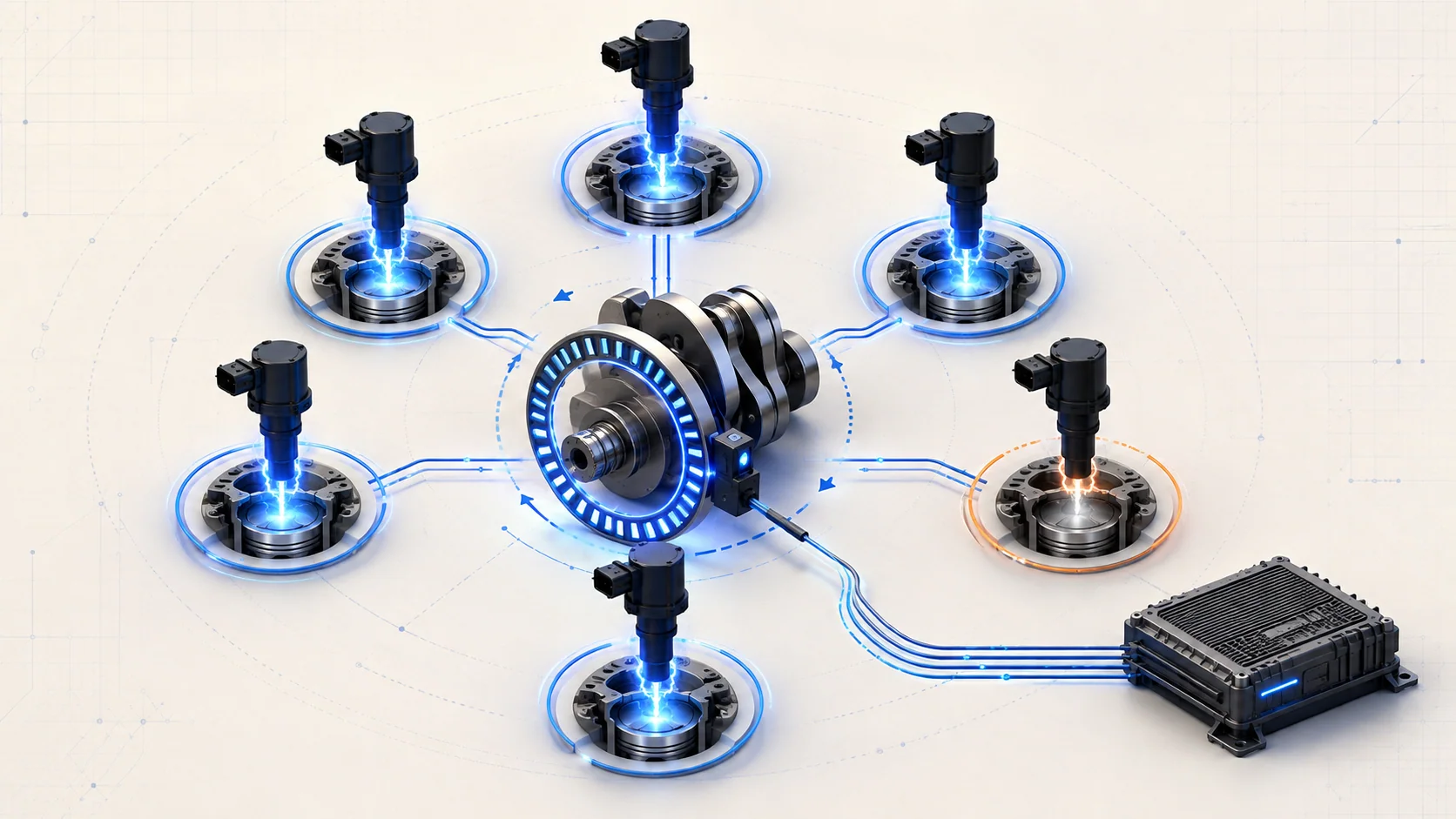
The powertrain control module (PCM) must deliver spark at the correct point in each cylinder's cycle and determine whether each combustion event produces the expected crankshaft acceleration. On the 2.7-liter EcoBoost F-150, that work connects coil-on-plug ignition, spark plugs, crankshaft and camshaft position signals, fuel delivery, airflow control, cylinder sealing, and the onboard misfire monitor.
Private service-information targets confirm 2015 and 2025 F-150 4WD 2.7L turbo endpoints, while the linked STEP guides use the 2015-2025 educational grouping. The detailed system description reviewed for this overview is from the exact 2025 target. Confirm the VIN, engine application, calibration, and current service information before applying a test or repair procedure. Connector details, scan-tool functions, specifications, and service steps can differ within the grouped range.
A misfire DTC reports a combustion-result problem. It does not automatically condemn a spark plug or ignition coil. The PCM can observe the crankshaft slowing during a weak cylinder event, but that same result can be caused by missing spark, incorrect fuel delivery, unmetered air, low compression, valve or timing trouble, contaminated fuel, or an input that prevents accurate monitoring.
The main functional sections
- PCM and ignition strategy: The PCM calculates spark timing from operating inputs and commands each coil. Base ignition timing is electronically controlled rather than mechanically adjusted.
- Coil-on-plug ignition: Each cylinder has a coil mounted at its spark plug. The PCM controls the coil's primary circuit; collapse of the magnetic field produces the secondary voltage that fires the plug.
- Spark plugs and coil boots: The plug gap, insulator, electrode condition, installation, and the boot's insulation path determine whether the spark reaches the combustion chamber without leaking to ground.
- CKP and CMP inputs: The crankshaft position (CKP) signal gives the PCM crank speed and position. The camshaft position (CMP) signal identifies the compression stroke and lets the PCM synchronize individual coil firing.
- Misfire monitor: The PCM evaluates small changes in crankshaft rotational acceleration after cylinder events. A weak event may be assigned to one cylinder or recorded as a random/multiple-cylinder misfire when it cannot be isolated.
- Fuel, air, and mechanical contributors: Injectors, fuel pressure and quality, intake sealing, boost plumbing, cylinder compression, valve operation, and mechanical timing all influence whether a commanded spark produces useful torque.
- Catalyst-protection response: A severe continuing misfire can overheat the catalytic converter. Depending on the detected fault and operating conditions, the PCM may flash the malfunction indicator and temporarily disable fuel to an affected cylinder.
How the PCM detects a misfire
The PCM does not place a combustion-pressure sensor in every cylinder. Instead, it uses the CKP signal to measure the time between position references and calculate crankshaft speed and acceleration. A normal firing event adds torque and changes crankshaft acceleration in a predictable way. An event that produces substantially less acceleration becomes a possible misfire.
The monitor compares cylinder events while accounting for engine speed, load, operating mode, and signal noise. Rough-road disturbances and driveline oscillation can resemble combustion variation, so supporting inputs and plausibility checks help prevent false attribution. CKP and CMP signals must be credible and synchronized, and the learned crankshaft profile must be available where required. A CKP signal problem or missing profile learn can therefore affect misfire monitoring without being an ignition-coil failure.
The code pattern matters. P0300 means the monitor found misfire activity that it could not reliably assign to one cylinder, or found a multiple-cylinder pattern. P0301, P0302, P0303, P0304, and P0306 identify the cylinder whose power contribution was judged low. A cylinder label narrows the test area; it still does not name the failed part.
What the related DTCs are telling you
| DTC | Diagnostic category | What it directs you to prove |
|---|---|---|
| P0300 | Random or multiple-cylinder misfire | Whether the pattern follows a shared ignition, fuel, air, sensor, mechanical, or operating-condition cause rather than one cylinder |
| P0301 | Cylinder 1 misfire | Whether cylinder 1 loses spark, fuel metering, compression, or another required condition |
| P0302 | Cylinder 2 misfire | Whether the fault remains with cylinder 2 and which system causes its low contribution |
| P0303 | Cylinder 3 misfire | Whether cylinder 3 has an ignition, injector, air-distribution, compression, or control fault |
| P0304 | Cylinder 4 misfire | Whether evidence isolates the problem to cylinder 4 and survives a controlled component comparison |
| P0306 | Cylinder 6 misfire | Whether cylinder 6 lacks one of the same required combustion inputs |
Cylinder 5 is part of the six-cylinder engine, but this overview links only the matching STEP DTC guides currently published for this vehicle configuration. Use the complete vehicle scan and current service information when a different cylinder or companion code is present.
What the driver or technician may notice
Possible observations include:
- a rough idle, shake, stumble, or hesitation;
- reduced power or uneven acceleration;
- extended cranking or a poor cold start;
- a steady malfunction indicator lamp;
- a flashing malfunction indicator during a catalyst-damaging misfire;
- fuel odor or abnormal exhaust behavior;
- one cylinder showing a repeated misfire count, or several cylinders rising together;
- a fault that appears only cold, hot, under boost, at idle, after refueling, or after recent service.
Symptoms help reproduce the condition, but they do not identify the failed section. A coil that breaks down only under cylinder pressure may look normal at idle. An injector or compression problem can imitate the same driveability complaint. Capture when and where the count increases.
Safety and catalyst protection
Do not continue loading an engine while the malfunction indicator is flashing or a severe misfire is active. Unburned fuel can overheat and damage the catalytic converter, dilute engine oil, and create a fire hazard around a damaged exhaust system. Move the truck only as needed for safe diagnosis.
Ignition coils can generate dangerous secondary voltage. Keep hands and improvised test leads away from an operating ignition system. Do not pull a coil or plug wire substitute from a running engine to look for spark. Use an approved spark tester and the exact service procedure.
Fuel systems can retain pressure, and the turbocharger and exhaust remain hot after operation. Follow the specified pressure-relief, battery, lifting, ventilation, and hot-component precautions. Secure the vehicle, keep tools and clothing clear of moving parts, and use insulated, terminal-safe probes.
Common failure categories
1. Spark plug or coil-on-plug fault
A worn, fouled, cracked, incorrectly gapped, loose, or contaminated spark plug can require more firing voltage than the system can reliably supply. A damaged boot, moisture or oil in the plug well, carbon tracking, weak coil, poor coil power or ground, damaged control circuit, or poor terminal fit can produce the same cylinder-specific result.
Inspect before swapping parts. Record plug condition and compare it with neighboring cylinders. A controlled swap can be useful only when the parts are compatible, identified, and moved one variable at a time. If the misfire follows the component, confirm the result before replacement. If it stays with the cylinder, stop swapping and test the remaining causes.
2. Fuel delivery or injector fault
Combustion can weaken because an injector is restricted, electrically inoperative, leaking, or commanded incorrectly. Low or unstable fuel supply, contaminated fuel, incorrect pressure, or a shared control problem can affect several cylinders. A single-cylinder code may also result from injector flow imbalance rather than a completely dead injector.
Use pressure data, fuel trims, injector circuit evidence, and the specified balance or functional test where available. Do not loosen a fuel connection to see whether fuel is present, and do not condemn a high-pressure component from a misfire code alone.
3. Unmetered air, charge-air leak, or uneven air distribution
An intake leak can lean one bank or several cylinders, while a localized manifold or sealing problem can affect one runner more strongly. On a turbocharged engine, charge-air leaks may become obvious only under load. PCV, purge, throttle, intake, and boost-control faults can alter the air charge and produce a misfire pattern without an ignition failure.
Compare fuel trims and misfire counts by bank, operating condition, and load. Inspect hoses, ducts, clamps, manifold sealing, and connected systems before replacing cylinder components.
4. Compression, valve, or mechanical timing fault
A cylinder cannot contribute normally if it cannot seal or move air correctly. Valve leakage, valvetrain damage, piston or ring problems, head-gasket leakage, cam timing errors, or other base-engine faults can create a persistent misfire that remains after ignition and injector checks.
Use relative compression as a screening tool, then confirm with the appropriate compression, leak-down, borescope, or mechanical-timing procedure. Do not disassemble the engine because one P030x code is stored; earn that step with repeatable evidence.
5. Position-signal, learned-profile, wiring, or PCM-input problem
The misfire monitor depends on CKP-derived crankshaft acceleration and CMP synchronization. Signal noise, intermittent wiring, terminal damage, incorrect sensor installation, a damaged timing target, or a missing crankshaft profile learn can distort the evidence used by the monitor. Related CKP, CMP, synchronization, or P0315 faults should be handled before treating the cylinder code as an isolated combustion failure.
A practical diagnostic sequence
1. Preserve the evidence
Scan all modules before clearing anything. Record P030x codes, companion ignition, injector, fuel-pressure, airflow, boost, CKP/CMP, timing, and network codes. Save freeze-frame or snapshot data and note coolant temperature, load, speed, fuel level, trims, and whether the warning lamp flashed.
2. Reproduce the pattern without abusing the catalyst
Determine whether the misfire occurs at cold start, warm idle, light cruise, acceleration, boost, deceleration, or after a heat soak. Watch cylinder misfire data and stop the test if the misfire becomes severe. A count on one cylinder suggests a focused comparison; counts across a bank or the whole engine point toward shared conditions.
3. Complete visual and service-history checks
Check battery condition, grounds, harness routing, connectors, intake and charge pipes, vacuum and PCV connections, fluid levels, fuel quality, and recent work. Inspect plug wells for oil or water and verify that coils, injectors, and connectors are fully seated. Look for evidence, not just disturbed parts.
4. Separate ignition from the cylinder
Inspect the plug and coil, then use approved spark and circuit tests. A controlled component swap may show whether the fault follows a plug or coil. Avoid moving several parts together because that destroys the diagnostic value of the comparison.
5. Prove fuel and air delivery
If ignition evidence is good, evaluate injector command and response, fuel pressure behavior, fuel trims, and intake or boost leakage. Decide whether the pattern is one cylinder, one bank, or system-wide. Follow the exact pressure-relief and injector test procedure for the vehicle.
6. Prove mechanical integrity and monitor inputs
For a misfire that stays with the cylinder, compare compression and cylinder leakage and inspect valve or timing evidence as directed. If related CKP, CMP, synchronization, or learned-profile codes are present, diagnose those first. A monitor that lacks reliable position information cannot provide reliable cylinder attribution.
7. Verify the repair under the original conditions
Clear codes only after preserving evidence and completing the repair. Recheck misfire data under the same temperature, load, and operating condition that produced the fault. Confirm that the code does not reset, the cylinder counts remain stable, no new companion DTC appears, and the flashing-lamp or catalyst-risk condition is gone.
Repair direction by confirmed cause
- Repair plug, coil, boot, connector, power, ground, or control-circuit faults only after the ignition path is proven.
- Repair injector circuits, fuel-supply faults, contamination, or injector flow problems using the exact fuel-system procedure.
- Repair intake, PCV, purge, charge-air, or sealing leaks found by inspection or an approved leak test.
- Correct compression, valve, timing, or internal-engine faults only after mechanical tests confirm them.
- Repair CKP/CMP circuits, targets, installation, or learned-profile issues before reevaluating the misfire monitor.
- Do not replace the PCM until its inputs, outputs, powers, grounds, circuits, calibration requirements, and directed tests support that conclusion.
Final takeaway
The useful question is not “Which part matches P030x?” It is “Why did this cylinder event produce less crankshaft acceleration?” Start with the code pattern and operating data, protect the catalyst, prove spark, then separate fuel, air, mechanical integrity, and monitor-input problems. That sequence turns a broad misfire complaint into a controlled diagnosis and prevents the most common failure: replacing ignition parts while the real cause remains in the cylinder, fuel system, air path, or position-signal evidence.