Applicability basis: Exact vehicle records confirm 2015 and 2025 Ford F150 4WD applications with the 2.7-liter turbocharged V6, supporting the public 2015-2025 vehicle/engine range used by STEP Diagnostics. Detailed system and diagnostic evidence for this overview was verified on the 2025 application. Exact component arrangement, oil-pressure specifications, signal patterns, connector information, scan-tool functions, timing procedures, learn prerequisites, and repair instructions can vary by model year and calibration; use current service information for the truck being repaired.
What the engine timing and VCT system does
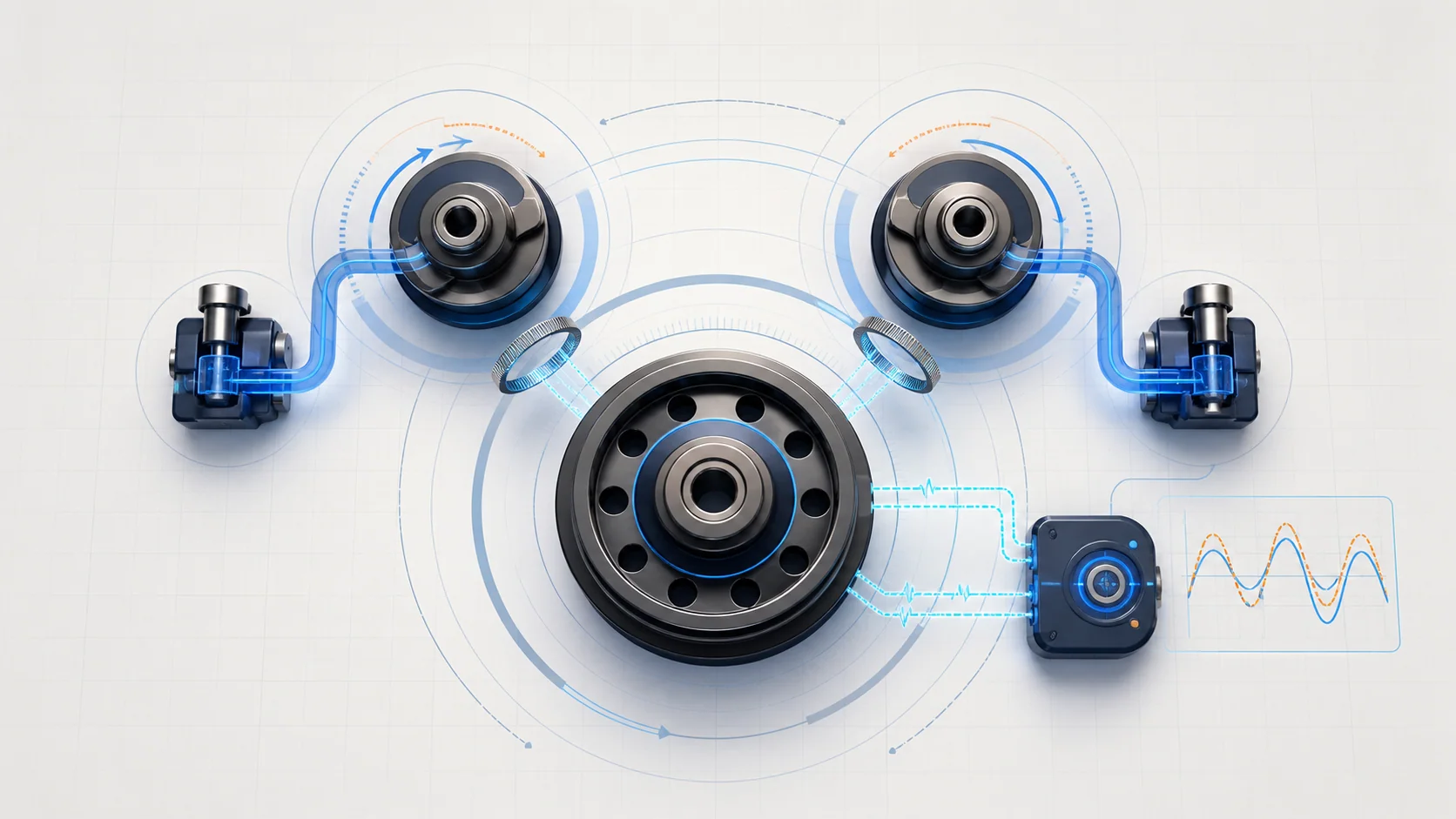
The engine has to keep two kinds of timing under control. First, the mechanical timing drive keeps the crankshaft and camshafts in the correct base relationship so the valves operate at the right point in each cylinder's cycle. Second, the variable camshaft timing (VCT) system changes camshaft phase while the engine is running so valve timing can suit different speed, load, temperature, and operating conditions.
The powertrain control module (PCM) manages and checks that process through several linked functions:
- A crankshaft-position input provides the primary reference for engine speed and crankshaft position.
- Camshaft-position inputs identify where the camshafts are relative to that crankshaft reference.
- The PCM commands VCT control hardware to route engine oil to the appropriate cam phaser.
- The phaser changes camshaft angle relative to its base mechanical relationship.
- The PCM compares desired cam position with the position reported through the camshaft signals.
- A learned crankshaft pulse-wheel profile helps the misfire monitor distinguish normal tooth-to-tooth variation from combustion-related speed changes.
These functions overlap, but they are not interchangeable. A circuit DTC, a cam-response DTC, a crank-to-cam correlation DTC, and a missing learned-profile DTC answer different diagnostic questions. None identifies the failed part by itself.
The main functional sections
- Mechanical timing drive: The crankshaft, timing drive, camshafts, phasers, and their indexed relationships establish base valve timing. Wear, incorrect assembly, target movement, or another mechanical shift can change correlation even when every electrical circuit is intact.
- Cam phasers: A phaser changes the angular relationship between its camshaft and the timing drive. It must move when commanded, hold a stable position, and return as the control strategy changes.
- VCT oil control: Engine oil is the working medium used to move the phasers. The VCT solenoids meter oil flow under PCM control. Oil level, condition, viscosity, pressure, restricted passages, debris, or a sticking control valve can therefore change cam response without creating a simple open-circuit fault.
- Crankshaft-position channel: The crankshaft sensor, pulse wheel, wiring, shielding where used, connectors, and PCM input create the crank reference. A missing, noisy, intermittent, or physically distorted signal can affect starting, synchronization, and misfire monitoring.
- Camshaft-position channels: The camshaft sensors, targets, supplies, signal paths, connectors, and PCM inputs report cam position. A signal problem can look like a timing problem until circuit integrity and signal quality are proved.
- PCM command and feedback logic: The PCM evaluates control-circuit integrity, requested and actual cam response, crank/cam correlation, synchronization, and the learned crankshaft profile. The exact PIDs, commands, limits, and monitor conditions are calibration-specific.
Normal operation in four layers
1. Base mechanical timing remains correct
Before VCT can work correctly, the timing drive must keep the crankshaft, camshafts, phasers, and position targets in their intended base relationship. VCT can move a cam through a controlled range; it cannot compensate for incorrect assembly, a shifted target, excessive mechanical movement, or damaged timing hardware.
2. The PCM requests a cam position
When operating conditions call for a timing change, the PCM controls the appropriate VCT solenoid. The solenoid directs pressurized engine oil within the phaser circuit, and the phaser advances or retards the camshaft relative to base timing. When the requested position changes, oil flow and phaser movement have to respond predictably.
This is why oil and electrical checks belong in the same diagnostic picture. A correct electrical command cannot move a phaser if the hydraulic path is restricted or pressure is inadequate. Good oil pressure does not prove that a solenoid circuit, solenoid, or phaser is working.
3. Position signals close the feedback loop
The PCM watches crankshaft and camshaft information while VCT operates. It can evaluate whether a usable signal exists, whether synchronization is established, whether actual cam movement follows the request, and whether the crank-to-cam relationship remains plausible.
A signal can fail in several ways. It can disappear, become intermittent or noisy, remain electrically present while its physical target is wrong, or report a credible position that does not match the commanded cam movement. Those distinctions explain why the related DTCs lead to different tests.
4. The PCM retains a crankshaft profile
The PCM can learn the small normal variations in the crankshaft pulse-wheel pattern. That learned profile supports misfire monitoring. A profile correction is a setup routine performed only when the crank signal, pulse wheel, starting system, and required operating conditions are credible.
The routine does not restore a missing signal, repair a damaged pulse wheel, correct shifted mechanical timing, or free a sticking phaser.
What the related DTCs are telling you
| DTC | Diagnostic category | What it directs you to prove |
|---|---|---|
| P0010 | Bank 1 intake VCT actuator/control-circuit fault | Whether the VCT solenoid, power supply, PCM control path, connector, harness, or module driver explains the electrical result before judging hydraulic or mechanical response |
| P0011 | Bank 1 intake cam timing over-advanced or performance fault | Whether actual intake-cam movement follows the request, and whether oil flow, oil pressure, the solenoid, phaser, or base timing explains a response that is slow, stuck, or out of range |
| P0014 | Bank 1 exhaust cam timing over-advanced or performance fault | Whether actual exhaust-cam movement follows the request, and whether the oil-control, solenoid, phaser, or mechanical side explains the result |
| P0016 | Bank 1 intake cam-to-crank correlation fault | Whether related position-signal faults are primary, base mechanical timing is correct, and VCT oil control and phaser response preserve the expected crank-to-cam relationship |
| P0315 | Crankshaft pulse-wheel profile not learned | Whether the PCM has a stable crankshaft signal and a mechanically credible pulse wheel before performing and verifying the applicable learned-profile correction |
| P0340 | Bank 1 intake camshaft-position circuit/signal fault | Whether power, ground or return, signal integrity, connector condition, harness routing, electrical interference, sensor operation, target relationship, or the PCM input explains the unusable cam signal |
The complete code set changes the order of work. A direct camshaft-signal fault can make a correlation or VCT-performance result secondary. A VCT control-circuit fault should be resolved before a technician condemns a phaser for failing to move. P0315 follows a separate CKP/profile path: establish battery and starting-system condition, confirm usable CKP-derived engine-speed information, address a CKP circuit or pulse-wheel concern when the directed test identifies one, and then perform the profile correction when directed.
What the driver or technician may notice
Possible observations include:
- a malfunction indicator lamp with little or no obvious drivability change;
- rough idle, hesitation, reduced power, or inconsistent response when cam timing should change;
- extended cranking, a no-start, or a synchronization complaint when a critical position signal is unavailable;
- an intermittent fault that appears with heat, vibration, harness movement, oil temperature, or particular engine speed and load;
- a VCT desired-versus-actual difference that remains large, changes slowly, or does not return as expected;
- a missing synchronization indication or unstable engine-speed data during cranking;
- a misfire monitor that cannot complete normally while the crankshaft profile is not learned;
- several VCT, CMP, CKP, correlation, oil-pressure, or misfire-related codes that need to be prioritized as a group.
These observations do not prove a phaser, solenoid, sensor, timing drive, or PCM has failed. Similar symptoms can come from lubrication, starting, charging, fuel, ignition, airflow, or base-engine faults.
Safety comes before timing diagnosis
Running VCT and signal tests can place the technician near belts, pulleys, the cooling fan, hot turbocharger and exhaust surfaces, and moving linkages. Secure clothing, test leads, and tools. Keep hands clear of rotating parts, and remember that an electric fan can start unexpectedly.
Do not apply power or ground to a VCT solenoid, back-probe a position circuit, or disconnect a PCM connector unless the exact Ford procedure identifies the correct component, terminals, fused test method, and vehicle state. A wrong jumper or test connection can damage a module driver, create unexpected cam movement, or corrupt the diagnosis.
Mechanical timing and phaser service can require extensive disassembly, controlled engine positioning, single-use fasteners, and careful handling of fuel, oil, coolant, intake, turbocharger, and electrical connections. Use current service information, support the vehicle and engine as directed, allow hot components to cool, and verify every disturbed connection before starting the engine.
Treat any crankshaft-profile correction or other scan-tool routine as a controlled service procedure. Keep the vehicle secured, use a fully charged battery, follow every enable condition and tool prompt, and stop if engine behavior, vehicle state, or the work area becomes unsafe.
Failure categories represented by these DTCs
1. The VCT electrical control path is faulty
An open circuit, excessive resistance, short to ground, short to voltage, poor terminal fit, corrosion, damaged connector, failed solenoid winding, or module-driver concern can prevent correct solenoid control. P0010 belongs here first. A circuit code is not proof that oil pressure or the phaser is the root cause.
2. Oil control cannot move or hold the phaser correctly
Low or unsuitable oil, pressure loss, debris, restricted passages, a sticking VCT solenoid, internal leakage, or a phaser concern can make actual cam position lag, stick, overshoot, or fail to return. P0011 and P0014 are response categories, so desired and actual movement matter more than a parts list.
3. A position signal is missing, noisy, or intermittent
Harness routing, electrical interference, connector condition, circuit faults, sensor failure, contamination, target damage, or an incorrect sensor-to-target relationship can corrupt CKP or CMP data. A clean static voltage reading does not prove that a signal remains usable during cranking, heat, vibration, or VCT movement.
4. The mechanical crank-to-cam relationship has shifted
Incorrect assembly, timing-drive wear or movement, damaged indexing features, target movement, or phaser hardware can shift correlation. Diagnose direct CKP/CMP and VCT-control faults first because the PCM cannot judge mechanical correlation reliably from a bad input or uncontrolled actuator.
5. The learned crankshaft profile is absent
The PCM may report the profile as not learned or missing after a relevant repair or setup event. Complete the correction only when the crank signal, pulse wheel, starting system, and relevant mechanical condition are credible. If the routine will not complete or remain stored, follow the exact P0315 diagnostic path rather than repeating it indefinitely.
6. A shared operating condition misleads the diagnosis
Battery or cranking performance, charging-system noise, engine oil condition, oil pressure, another cam or crank DTC, or recent repair work can change several test results at once. These shared influences should be understood before multiple components are replaced.
A practical system-first diagnostic strategy
Step 1: Confirm the exact application and preserve evidence
Verify model year, engine, drivetrain, installed calibration, recent repairs, oil specification and service history, and the applicable Ford procedure. Save confirmed, pending, and history DTCs with freeze-frame or failure-record data before clearing anything. Note starting behavior, engine speed, temperature, load, desired and actual VCT data, synchronization status, battery condition, and whether the concern followed timing, sensor, module, battery, or oil-system work.
Step 2: Classify and prioritize the code set
Separate direct VCT circuit faults, CMP/CKP signal faults, VCT performance faults, correlation faults, and learned-profile faults. Follow the related-code priorities in current service information. For VCT and correlation diagnosis, establish power and signal integrity before judging actuator response, then establish actuator and position-signal credibility before judging mechanical correlation. Treat P0315 as its own CKP/profile path rather than making VCT or oil-system checks universal prerequisites for the profile correction.
Step 3: Check oil and basic engine condition early
Verify oil level and condition and confirm that the oil matches the exact application. Look for an incorrect filter, contamination, aeration, sludge, or evidence of pressure trouble. If the directed path calls for a mechanical oil-pressure test, use the correct adapter, specification, temperature, and safety procedure. Do not condemn a phaser from scan data alone when the oil supply has not been evaluated.
Step 4: Inspect without destroying intermittent evidence
With the engine safely off, inspect accessible VCT and position-sensor harness routing, connectors, retainers, heat exposure, shielding where used, grounds, chafe points, oil intrusion, and recent service areas. Document connector position and condition before disconnecting it. Inspect accessible sensor seating and mechanical areas only as current service information allows.
Step 5: Use scan data as a command-versus-response test
Observe the relevant desired, actual, difference, synchronization, and engine-speed parameters. Reproduce the stored operating region only when safe. Ask focused questions:
- Does the PCM see a stable crankshaft signal during cranking and running?
- Is cam/crank synchronization established?
- Does actual cam position move when VCT is requested?
- Does it follow the request and return without a persistent error?
- Is the problem limited to one cam, one bank, one electrical circuit, or a shared condition?
Use the exact PID names, command limits, and test conditions for the truck. A brief change during a rapid command is not automatically a failed response.
Step 6: Prove circuits and components with the directed test
For P0010 or P0340, use the exact wiring diagram and specified test method to prove the supply, control or signal path, return or ground, connector integrity, and shorts before replacing a component. For an intermittent concern, monitor relevant data during a controlled harness-movement or noise check while keeping all leads and hands clear of moving parts.
For a VCT performance concern, distinguish an electrically working solenoid from a hydraulically effective system. The directed procedure may require controlled solenoid actuation, oil-pressure evaluation, and comparison of cam movement. Do not improvise a jumper or assume that audible or tactile solenoid movement proves the phaser and oil path are healthy.
Step 7: Separate correlation, mechanical timing, and profile learn
For P0016, confirm that the position signals and VCT control are credible, then follow the exact base-timing, phaser, target, and timing-drive checks. For P0315, confirm a stable crankshaft signal and credible pulse wheel, satisfy every prerequisite, and run the specified profile correction. A successful correction does not validate mechanical timing, and a failed correction does not automatically condemn the PCM.
Step 8: Verify the complete repair
Reconnect and secure every disturbed circuit, shield, retainer, oil passage component, intake connection, fluid connection, and mechanical fastener. Complete required memory resets, profile corrections, programming, or other setup steps. Clear codes when directed, repeat the self-test, reproduce the relevant operating region, and confirm that desired/actual VCT and synchronization data remain credible and no related pending DTC returns.
A cleared warning light or a good idle before the monitor runs is not repair verification.
Match the repair to the proven failure
The supported repair may be a terminal or harness repair, restored supply or control circuit, corrected harness routing or shielding, proper oil and filter service, an oil-pressure or oil-flow repair, cleaned or replaced VCT control hardware, corrected sensor installation, sensor replacement, repaired target or timing drive, phaser service, completed profile correction, or—only after the directed branches support it—PCM repair or replacement with required programming and setup.
Avoid common shortcuts:
- replacing a VCT solenoid for every P0010 without proving the circuit;
- replacing a phaser for every P0011 or P0014 without checking oil supply and commanded response;
- treating P0016 as proof that the timing drive has jumped before signal and VCT faults are resolved;
- replacing a camshaft sensor for every P0340 without checking power, signal integrity, connector condition, routing, and interference;
- using a profile correction as a repair for a bad CKP signal or pulse wheel, or expecting it to repair a separate CMP, VCT, oil-pressure, or mechanical-timing fault.
Final takeaway
On the 2015-2025 Ford F150 2.7 EcoBoost, engine-timing diagnosis is a layered evaluation of base mechanical timing, oil-controlled cam phasing, VCT electrical control, crankshaft and camshaft signal quality, command-versus-response behavior, crank-to-cam correlation, and a learned crankshaft profile.
Start with the complete code set and stored evidence. For VCT and correlation concerns, prove basic oil and electrical conditions, use scan data to separate a circuit fault from a response fault, establish credible CKP/CMP signals, and only then move into correlation or mechanical timing. For P0315, follow the separate CKP/profile path and perform the correction when that directed test supports it. The linked STEP DTC guides provide model-specific educational paths; current service information for the exact truck controls specifications, connector references, commands, disassembly, setup, and final verification.