Applicability basis: Exact vehicle records confirm 2015 and 2025 F150 4WD applications with the 2.7-liter turbocharged V6, supporting the public 2015-2025 vehicle/engine range used by STEP Diagnostics. Detailed system and diagnostic evidence for this overview was verified on the 2025 application. Exact valve arrangement, tank and canister layout, scan-tool functions, monitor strategy, connector information, test values, and repair procedures can vary by model year, tank configuration, emissions calibration, and installed equipment; use service information for the truck being repaired.
What the EVAP system does
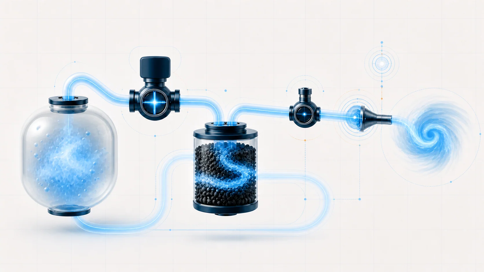
The evaporative-emissions system keeps gasoline vapor from venting directly to the atmosphere. It contains and controls vapor from the fuel-storage system, routes vapor to a charcoal canister, and later meters the stored vapor into the engine so it can be burned.
That simple description hides two separate jobs:
- Vapor management: Store vapor safely, admit filtered air when needed, and purge the canister without upsetting engine operation or pressurizing the fuel tank.
- Self-diagnosis: Command known valve states, observe fuel-tank pressure, and decide whether the system flows and seals as expected.
The powertrain control module (PCM) does not directly see a cracked hose or a leaking seal. It sees pressure behavior. A diagnostic trouble code (DTC) therefore describes the result of a monitor—too much flow, too little response, failure to reach a target, or excessive pressure change after sealing—not the failed component by itself.
The main functional sections
- Fuel tank, filler, and vapor-control hardware: The tank and filler area must contain liquid fuel while allowing vapor to leave through controlled passages. The exact arrangement can change with tank option and model year. Capless-filler seals, check valves, rollover protection, and tank-mounted vapor hardware can all affect sealing and airflow.
- Vapor lines: These tubes connect the tank, canister, vent path, purge path, and intake. A line can leak, collapse, kink, become restricted, be misrouted after service, or contain liquid fuel.
- EVAP canister: Activated charcoal stores fuel vapor when purge is unavailable. A saturated, contaminated, cracked, or restricted canister can create flow and sealing problems.
- Fresh-air and vent path: A normally open canister vent path admits filtered air during normal operation. The control module closes the vent valve when it needs to seal the system for a test. The verified late application also uses a normally open vapor-blocking valve between the tank and canister. The PCM can close it to purge the canister without purging the tank, then open it when tank vapor flow or pressure or vacuum relief is required. Earlier model years may arrange or name the isolation hardware differently.
- Purge path: The purge valve meters stored vapor toward the engine. It must remain sealed when commanded closed and provide controlled flow when commanded open.
- Turbocharged-engine protection and purge assistance: On the verified late 2.7 EcoBoost application, a check valve prevents boost pressure from entering the EVAP system, while an ejector arrangement can create purge-line vacuum during boost. These parts let purge continue under operating conditions where the intake manifold itself is pressurized. Earlier model years may arrange or name these parts differently.
- Fuel-tank pressure feedback: The fuel-tank pressure sensor reports tank pressure or vacuum to the PCM. It is the primary feedback device for purge-flow and leak-monitor decisions.
- PCM strategy: The PCM considers operating conditions and fuel level, commands the purge and vent functions, and evaluates how quickly tank pressure changes. Some late applications also use an engine-off natural-vacuum strategy after shutdown.
Normal operation in four stages
1. Vapor is stored
Fuel evaporates whenever temperature, agitation, and tank conditions allow it. When the strategy allows tank-to-canister flow, vapor leaves the tank through vapor-control passages and travels to the charcoal canister instead of escaping outside. The vent and any tank-isolation hardware manage the air and vapor paths so the system can store vapor, purge the canister, and control tank pressure.
2. The PCM meters purge
When engine and monitor conditions are suitable, the PCM opens the purge valve by a controlled amount. Intake-system vacuum draws vapor out of the canister and into the engine. On the turbocharged 2.7 EcoBoost, the check-valve and ejector paths protect the tank from boost and provide a usable purge path when the intake manifold is not under vacuum.
Purge is not simply ON or OFF. The PCM requests an amount of flow appropriate for operating conditions. During a monitored test that is intended to change tank pressure, it expects the fuel-tank pressure response to agree with the commanded state.
3. The system is sealed for a monitor
To test the system, the PCM closes the atmospheric vent path and uses controlled purge or naturally occurring tank-pressure change to create a known condition. It then watches the pressure sensor to determine whether the expected target is reached and whether the sealed system retains it.
On the verified 2025 configuration, the strategy can evaluate EVAP behavior with the engine running and can also use pressure or vacuum that develops naturally after shutdown. Do not assume every model year uses identical enable conditions, test sequence, or failure thresholds.
4. Pressure behavior is classified
The monitor can recognize several different patterns:
- the system cannot reach the requested vacuum;
- vacuum develops faster or farther than expected;
- the sealed system loses vacuum too quickly;
- commanded purge produces too little pressure response;
- tank pressure appears implausible even when the system is opened to atmosphere;
- a valve or circuit does not respond to command.
Those patterns create diagnostic categories. The component still has to be proven.
What the related DTCs are telling you
| DTC | Monitor category | What the technician needs to prove |
|---|---|---|
| P0441 | Incorrect purge-flow behavior; the verified 2025 source uses subtype 9B for high/excessive flow, while subtype wording and monitor interpretation can vary by year | Whether the FTP baseline is credible, the vent path is unrestricted, the purge valve seals when closed, and commanded purge produces the expected tank-pressure response |
| P0442 | Small-leak result | Whether the filler, lines, canister, tank, valves, and connections seal under the specified test conditions, and whether vapor generation or setup affected the result |
| P0455 | Large-leak or inability-to-reach-target category | Whether there is a gross opening, incorrect connection, open sealing point, failed valve, no purge flow, biased FTP signal, or restriction that prevents the monitor from establishing its target |
| P0456 | Very-small-leak result | Whether a small sealing defect is present and repeatable after the system and test equipment are set up correctly |
| P0496 | Excessive purge flow or excessive tank-vacuum response | Whether the purge valve leaks when closed, a vent or vapor path is restricted, the FTP signal is biased, or the commanded and actual valve states disagree |
These codes overlap because one physical fault can change more than one monitor result. A purge valve that leaks when closed may create excessive tank vacuum, affect startup after refueling, and prevent a leak test from starting normally. A vent restriction can look like excessive purge. A biased FTP signal can make a sealed system appear to leak or make a normal purge response appear excessive.
What the driver or technician may notice
Common observations include:
- a malfunction indicator lamp with no obvious drivability complaint;
- an incomplete EVAP readiness monitor;
- fuel odor near the filler, tank, canister, vapor lines, or engine compartment;
- possible startup or fueling complaints after refueling when an unwanted-purge concern is present;
- abnormal tank vacuum or pressure, sometimes noticed when refueling;
- a fault that returns only after a long soak, a particular fuel level, a temperature change, or the monitor's next valid opportunity to run;
- multiple EVAP DTCs whose combination is more useful than any one code alone.
None of these observations proves that the purge valve, canister, pressure sensor, or fuel tank has failed. EVAP faults can be intermittent and strongly dependent on fuel level, temperature, soak time, and operating state.
How the system commonly fails
1. The system has an external leak
A damaged vapor line, loose connection, cracked canister, tank or filler damage, sealing debris, or a cap/capless-filler concern can let air enter or vapor escape. Large openings are usually easier to locate; very small leaks demand careful test setup and patient inspection.
2. The purge valve does not seal
A purge valve can pass an electrical check yet leak mechanically. When it flows while commanded closed, engine vacuum can reach the tank at the wrong time. That can produce excessive-vacuum evidence and can change startup behavior after refueling.
3. Commanded purge is restricted or absent
A stuck valve, blocked valve port, collapsed line, liquid fuel, canister restriction, or circuit fault can prevent the expected tank-pressure change. A large-leak/no-flow monitor result is not proof of a hole until purge capability and sensor credibility are understood.
4. The vent or fresh-air path is restricted
Dust, debris, water, a kinked hose, damaged filter, stuck valve, or contaminated canister can prevent the system from breathing. A restriction can create excessive tank vacuum and can also distort smoke or pressure testing.
5. The FTP signal is biased or intermittent
The pressure sensor, reference supply, low-reference path, signal circuit, connector, or PCM input can report a false tank condition. Establishing a credible atmospheric baseline before commanding vacuum is one of the most useful ways to avoid misdiagnosis.
6. Turbo purge hardware does not control flow correctly
On applications using a boost check valve and ejector, a failed check function, restricted ejector path, or incorrect hose routing can affect purge during boost. Diagnose these parts with the exact service procedure; do not pressure-test the system with improvised connections.
7. The canister or vapor plumbing contains liquid fuel
If liquid fuel enters components intended for vapor, it can change system airflow and prevent smoke or test gas from moving through the system normally. Use the exact service procedure to identify the source and determine which contaminated components require service.
A practical system-first diagnostic strategy
Step 1: Confirm the exact truck and preserve evidence
Verify model year, engine, drivetrain, tank configuration, emissions calibration, and installed EVAP hardware. Record confirmed, pending, and history DTCs along with freeze-frame or failure-record data before clearing anything. Note recent refueling, fuel level, outside temperature, soak time, recent tank or engine work, and whether the complaint occurs after refueling or only after shutdown.
Step 2: Classify the code set
Separate the concern into leak/sealing, excessive vacuum or unwanted purge, inadequate purge, vent restriction, circuit fault, and sensor plausibility categories. Diagnose shared electrical faults and direct valve/sensor circuit DTCs before treating a leak-size code as an isolated mechanical leak.
Step 3: Inspect the high-value areas without disturbing evidence
Inspect the capless filler or cap if equipped, filler neck, vapor lines, quick connections, tank area, canister, vent inlet/filter, purge plumbing, boost-related EVAP hoses, and recent service areas. Look for debris, pinching, chafe, heat damage, incorrect routing, disconnected lines, liquid fuel, and signs that a component has been forced or installed incorrectly.
Do not disconnect an intermittent connection until its original position and condition are documented.
Step 4: Establish a credible pressure baseline
Before judging purge-induced vacuum, vent the fuel tank and EVAP vapor space to atmosphere through the specified fuel-filler method, then allow pressure to equalize. Compare the FTP reading with the applicable service specification. If the baseline is wrong, resolve sensor/circuit plausibility before using that signal to condemn a valve or leak.
Step 5: Use bidirectional controls as a command-versus-response test
When supported, use the scan tool to command the vent and purge functions while watching FTP data. Ask specific questions:
- Does the purge valve remain sealed when commanded closed?
- Can the vent path close and allow vacuum to develop?
- Does a controlled purge request change tank pressure in the correct direction?
- Does tank vacuum remain within the safe limit identified by the service procedure?
- Does the pressure recover when the system is vented?
Use the exact command limits and time limits for the truck. Excessive commanded purge with the vent closed can damage components or create unsafe tank vacuum.
Step 6: Separate leak localization from leak verification
Smoke helps locate where a system leaks. A calibrated pressure/flow test determines whether the leak rate is acceptable. Those are different jobs.
Use only EVAP-approved equipment and the connection point specified by current service information. First prove that the tool connection itself does not leak and that the vent path can be controlled. Follow the full vapor path, move accessible hoses and connections, and remember that liquid fuel or internal check valves can prevent smoke from reaching every area.
After a repair, repeat the quantitative verification test. Seeing smoke stop at one point is useful evidence, but it does not prove that a second leak is absent.
Step 7: Match the repair to the proven failure
The supported repair may be cleaning a filler seal or vent inlet, restoring hose routing, repairing a line or terminal, correcting a connector, replacing a leaking valve, repairing a pressure-sensor circuit, replacing damaged tank-mounted vapor hardware, or addressing a contaminated canister. Replace the PCM only after the directed circuit and component branches support that conclusion.
Step 8: Verify under valid monitor conditions
Reconnect every line, electrical connector, retainer, shield, and disturbed intake connection. Clear codes only when the procedure calls for it, run the available EVAP service test, and complete the applicable repair-verification drive cycle or monitor conditions. Recheck pending codes and FTP behavior.
A cleared warning light is not a completed repair verification. The monitor must receive a valid opportunity to evaluate the system.
Safety and equipment cautions
Gasoline vapor is flammable. Work in a ventilated area away from sparks, flame, hot exhaust and turbocharger surfaces, and other ignition sources. Relieve fuel-system pressure before opening any fuel-system connection when the service procedure requires it, and be prepared to contain spilled fuel.
Do not use shop air, oxygen, or an unregulated pressure source to test the tank. Use approved EVAP leak equipment and the specified inert-gas or smoke procedure. Never exceed the test pressure or vacuum limits for the exact vehicle. Some leak-detection or isolation components can be damaged if smoke is applied through the wrong connection.
Keep the vehicle secured during running tests, route leads away from belts and fans, and stop if tank pressure, engine behavior, tool response, or system configuration does not match the procedure.
Common diagnostic mistakes
- Replacing the purge valve for every EVAP code without proving whether it leaks closed, flows when commanded, or has a circuit fault.
- Smoke-testing before verifying that the FTP signal, vent command, tool connection, and test setup are credible.
- Treating P0442 and P0456 as component names instead of different monitor thresholds.
- Overlooking a restricted vent path when tank vacuum is excessive.
- Assuming a passed electrical resistance check proves that a valve seals mechanically.
- Applying a 2025 component layout, scan command, or threshold unchanged to an earlier truck.
- Clearing codes and returning the vehicle before the EVAP monitor has run.
Final takeaway
On the 2015-2025 Ford F150 2.7 EcoBoost, EVAP diagnosis is a study of controlled vapor flow and pressure response. The PCM commands purge and vent states, watches the fuel-tank pressure signal, and decides whether the system can create, hold, and release the expected vacuum or pressure.
Start with the complete code set and stored conditions. Inspect sealing and routing, establish a trustworthy atmospheric FTP baseline, prove valve behavior with controlled commands, and use smoke localization separately from calibrated leak verification. The linked STEP guides provide the code-specific educational paths; current service information for the exact truck controls component layout, values, commands, equipment connections, repair instructions, and final verification.