Knock feedback lets the powertrain control module (PCM) use engine-vibration information when controlling spark timing. On the Ford F-150 2.7 EcoBoost, a knock-sensor circuit concern is not the same thing as proven combustion knock. A code alone does not establish that a sensor needs replacement, and a noise complaint alone does not identify an electrical fault.
This educational overview covers STEP's 2015–2025 F-150 2.7 EcoBoost library. Early and late configuration checks support the model-and-engine scope, not identical wiring or procedures throughout the range. Confirm the actual model year, engine, drivetrain and calibration before using service information. Exact connector identification, sensor location, test limits, monitor conditions and repair procedures must come from the information applicable to the vehicle being repaired.
What the system does
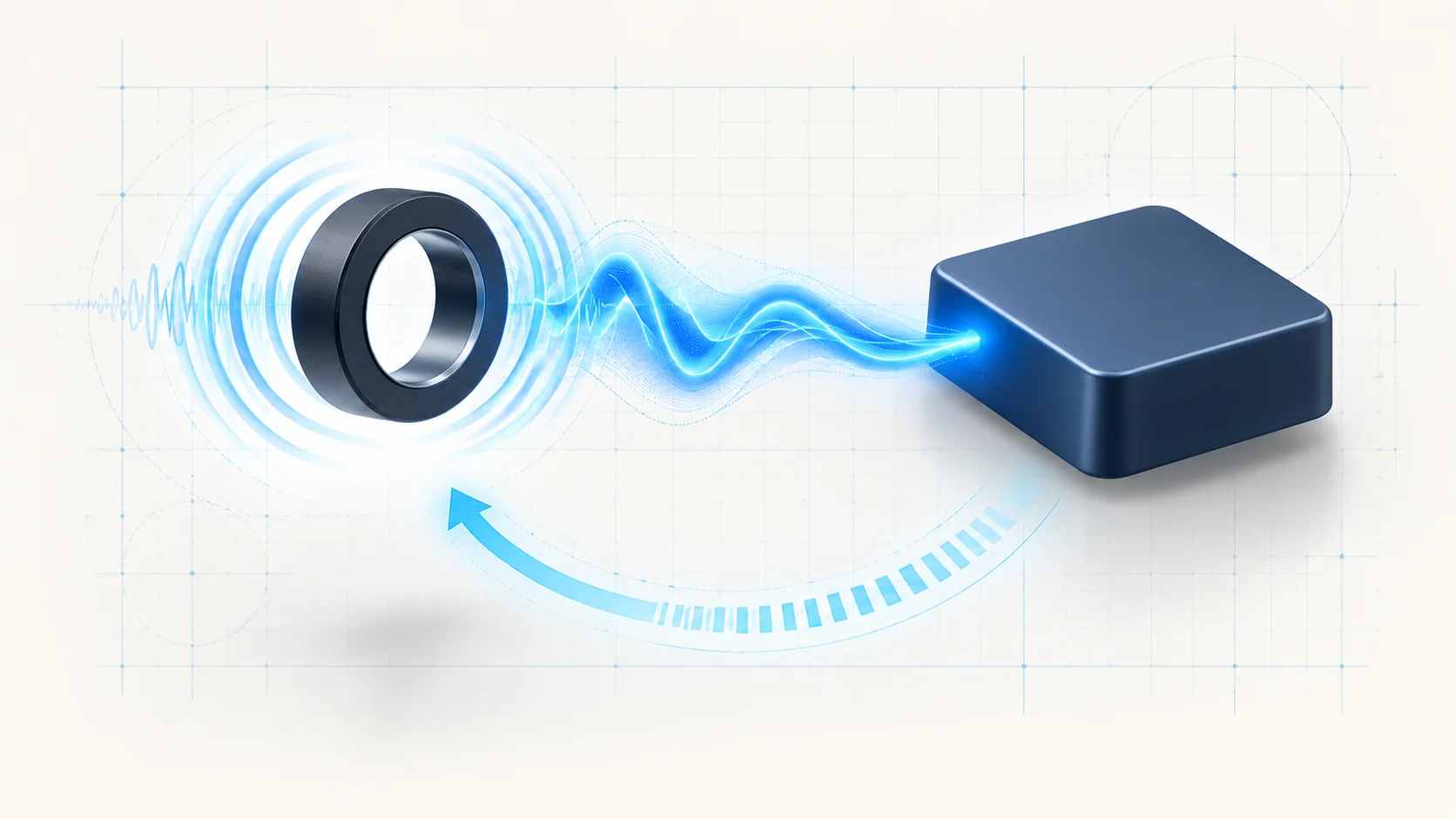
The knock sensor converts engine vibration into an electrical input. The PCM uses that information to recognize knock and retard spark timing. The useful diagnostic model is therefore a mechanical vibration input, an electrical signal path and a controller response. All three need to be considered; replacing one component does not automatically resolve every kind of knock-related concern.
Do not confuse ordinary engine vibration, an abnormal mechanical noise and combustion knock. Nor should a change in spark timing be treated as a direct measurement of a failed sensor. Interpret available scan data with the operating conditions and the complete fault picture.
The sensor's installation is part of the measurement system. Correct mounting and the prescribed installation procedure matter. This overview intentionally gives no universal mounting torque, sensor position or cylinder-bank assignment.
How the related codes fit
P0325 Diagnostic Guide introduces a concern with the expected knock-sensor signal. The late-endpoint diagnostic listing distinguishes sensor A circuit faults and their subtypes. Preserve the complete code, including any subtype, rather than assuming every P0325 entry uses the same failure logic.
P0330 Diagnostic Guide covers the other related signal concern. The late-endpoint listing identifies sensor B circuit faults. Do not turn those channel names into a physical sensor location without the applicable component and wiring information.
These STEP guides provide a route into diagnosis, not permission to transplant their exact pin numbers, resistance limits or road-test instructions to every F-150 in the catalog range. Confirm the source target and current service procedure before performing a test. The overview keeps the electrical-fault path separate from investigation of actual knock or other engine noise.
Failure categories and possible symptoms
Start by separating installation, wiring and connector integrity, sensor condition, and the underlying engine or operating condition. An open circuit, unwanted electrical connection or intermittent terminal contact can prevent trustworthy feedback. A damaged sensor is possible, but it is not proved by the DTC name. A controller concern requires the supporting diagnostic results and correct connector checks before replacement is considered.
The complaint may be an illuminated malfunction indicator lamp with little noticeable change in driving. Reduced performance or timing-control changes may also be reported. Neither symptom identifies the root cause. An intermittent concern may only return under particular operating conditions, so a quiet idle or a cleared code is weak evidence of a completed repair.
If the complaint is audible engine noise, investigate it as a separate symptom. Review operating conditions and relevant fuel, temperature, ignition, injection and mechanical evidence instead of assuming that knock-sensor replacement will remove the noise. Possible causes are investigative categories, not a list of parts to replace.
A practical diagnostic strategy
Preserve the original scan report, full code descriptions and available environmental data before clearing anything. Confirm the actual vehicle configuration and determine whether other engine faults change the starting point. Record when the symptom happens and distinguish a current circuit concern from an intermittent event or a noise-only complaint.
Inspect accessible wiring, connectors and sensor installation using the applicable service information. Look for evidence of damage, disturbed connections or poor terminal contact without assuming that an apparently clean connector is electrically sound. Keep the code's channel identification attached to the correct circuit throughout testing.
Follow the vehicle-specific electrical test sequence with the required isolation and adapters. Continuity, short-circuit and signal checks answer different questions. Do not substitute a generic resistance test, apply voltage to a signal circuit or copy a pin assignment from another engine. Resistance measurements require the prescribed power-off and circuit-isolation conditions; powered measurements require the correct meter mode and reference points.
Where the applicable diagnostic branch calls for knock-related scan data, interpret it with the recorded conditions and any audible symptom. Do not mix a circuit decision tree with an unrelated load-test branch. The existence of a road-test step in a guide does not make it appropriate for an engine already showing severe knock, overheating or another damaging condition.
Repairs and verification
Repair the demonstrated fault: a damaged circuit, connector or terminal, an installation concern, or a sensor supported by the tests. An established engine or operating-condition problem needs its own repair. Controller replacement and programming are separate, evidence-dependent operations, not a shortcut when the first checks are inconclusive.
Use the exact installation and tightening requirements for the vehicle. After repair, check disturbed connections, complete the prescribed self-test or verification procedure, and reassess the original complaint under safe, applicable conditions. Code clearing alone is not verification. Save the post-repair results alongside the original evidence so that an intermittent return can be compared meaningfully.
Safety and limits
Allow hot components to cool, keep clear of rotating components and follow the applicable electrical isolation procedure. Secure the vehicle with approved support if access requires working underneath it. Do not disconnect or probe controller circuits casually; unsuitable probes can damage terminals and create a new intermittent fault.
Stop testing if persistent severe knock, overheating or another condition threatens engine damage. Do not disable monitoring, alter calibration or repeatedly erase faults to mask the complaint. The goal is a reliable feedback signal and a verified repair, using the correct service information for the actual truck.