What the oxygen-sensor and catalyst-monitoring system does
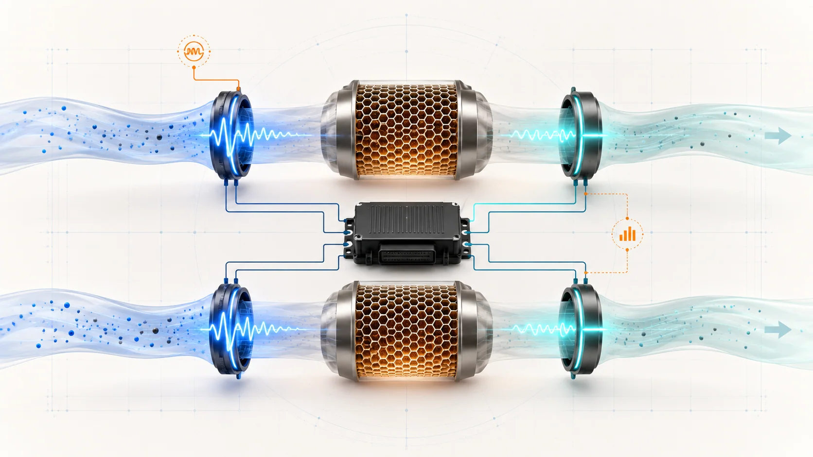
The powertrain control module (PCM) must control the air-fuel mixture, verify that the oxygen sensors are operating, and determine whether each bank's monitored catalyst system is storing oxygen and treating exhaust as expected. On the 2.7-liter EcoBoost F-150, these jobs connect the upstream universal heated oxygen sensors (UHO2S), downstream oxygen sensors, sensor heaters, exhaust sealing, fuel control, combustion quality, and the bank-specific catalyst monitors.
Private service-information targets confirm 2015 and 2025 F-150 4WD 2.7L turbo endpoints, while the linked STEP guides use the 2015-2025 educational grouping. The detailed diagnostic paths reviewed for this overview are from the exact 2025 application. Confirm the VIN, engine application, emissions calibration, sensor terminology, connector information, and current service procedure before testing or replacing anything. Those details can differ within the grouped range.
An oxygen-sensor or catalyst DTC identifies a behavior the PCM could not verify. It does not automatically prove that the named sensor or catalytic converter has failed. Electrical faults, exhaust leaks, mixture problems, misfire, oil or coolant consumption, fuel contamination, wiring damage, and previous repairs can all change the evidence seen by the monitor.
The main functional sections
- Upstream universal heated oxygen sensors: A UHO2S ahead of the monitored catalyst system on each bank provides wide-range exhaust feedback quickly enough for the PCM to correct fueling. Ford service information may use UHO2S, HO2S, O2 sensor, or related air-fuel-ratio terminology depending on the exact application and diagnostic path.
- Downstream oxygen sensors: A downstream sensor reports oxygen content after the monitored catalyst section for its bank. Its response is used for catalyst monitoring and other emissions checks rather than serving as the primary short-term fuel-control input. Confirm the exact converter and sensor arrangement from current service information.
- Sensor heaters: Each heated sensor needs to reach and maintain its operating temperature. The PCM monitors heater circuits so the sensors can become useful promptly after startup and remain responsive during low-flow conditions.
- Bank 1 and Bank 2 exhaust paths: The V6 has two cylinder banks. P0420 concerns the monitored Bank 1 catalyst path; P0430 concerns Bank 2. Bank and sensor designations must be confirmed from current service information before physical testing.
- Catalytic converters: The catalysts promote chemical reactions that reduce regulated pollutants. Their oxygen-storage and conversion behavior changes the relationship between upstream and downstream sensor activity.
- PCM monitors and enable conditions: The PCM judges sensor circuits, heater operation, mixture control, and catalyst efficiency only when the required operating conditions and prerequisite signals are valid.
How feedback control and catalyst monitoring work together
The upstream sensor responds to oxygen in the exhaust before it enters the catalyst. The PCM uses that information with airflow, pressure, temperature, fuel-pressure, and other inputs to adjust injector delivery. Normal closed-loop control continually corrects the mixture rather than holding one fixed sensor value.
The catalyst temporarily stores and releases oxygen while converting exhaust pollutants. A healthy catalyst therefore changes and dampens the oxygen pattern that reaches the downstream sensor. Once enable conditions are satisfied, the PCM evaluates the relationship between the upstream and downstream signals. The exact calculation, thresholds, and drive conditions are calibration-specific; a visual impression that two graph lines look similar is not a complete catalyst test.
Heaters are supporting systems, not catalyst-efficiency measurements. A heater fault can delay sensor readiness or prevent a monitor from running correctly. A high-voltage downstream-sensor code is also a circuit or signal diagnosis, not a direct catalyst verdict. Resolve those faults and any mixture or misfire problem before interpreting P0420 or P0430.
What the related DTCs are telling you
| DTC | Diagnostic category | What it directs you to prove |
|---|---|---|
| P0053 | Bank 1 Sensor 1 heater-resistance fault | Whether the upstream heater circuit, terminals, wiring, power/control path, and sensor heater satisfy the exact test before replacing the sensor |
| P0135 | Bank 1 Sensor 1 heater-circuit fault | Whether the PCM can control and observe the upstream heater circuit and whether a shared supply or wiring issue affects it |
| P0138 | Bank 1 Sensor 2 circuit high voltage | Whether the downstream signal is genuinely high because of exhaust conditions or is biased by a short, open reference path, connector problem, contamination, or sensor fault |
| P0141 | Bank 1 Sensor 2 heater-circuit fault | Whether the downstream sensor heater, its shared feed, control circuit, terminals, and PCM observation are correct |
| P0420 | Bank 1 catalyst efficiency below threshold | Whether prerequisite faults, exhaust leakage, mixture or combustion problems, sensor evidence, or actual Bank 1 catalyst degradation explains the failed monitor |
| P0430 | Bank 2 catalyst efficiency below threshold | The same diagnostic separation for the Bank 2 exhaust path |
This classification prevents two common errors: replacing a catalyst before proving the engine is producing suitable exhaust, and replacing an oxygen sensor merely because its signal helped the PCM detect a catalyst problem.
What the driver or technician may notice
Possible observations include:
- a malfunction indicator lamp with little or no immediate driveability change;
- delayed closed-loop operation or a monitor that remains incomplete;
- increased fuel consumption, hesitation, roughness, or unstable fuel trims when an upstream feedback fault affects mixture control;
- an exhaust odor, abnormal heat, or catalyst rattle when physical damage is present;
- reduced power at higher load if the exhaust is restricted;
- heater or circuit codes that appear soon after startup;
- P0420 or P0430 that returns only after the required monitor conditions are met;
- companion rich, lean, misfire, fuel-pressure, temperature, airflow, or sensor DTCs.
The symptom pattern guides test order but does not identify the failed part. A catalyst-efficiency DTC may be the downstream consequence of a problem elsewhere in the engine.
Safety before exhaust and sensor testing
Exhaust manifolds, turbocharger areas, sensors, pipes, and catalytic converters can remain hot long after the engine is shut down. Allow adequate cooling and use heat-resistant protection. Support the truck at approved lifting points before working underneath it; never rely on a jack alone.
Operate the engine only in a ventilated area with exhaust extraction where required. Keep combustible materials away from the exhaust. Do not create an exhaust leak, apply an open flame, or spray flammable products around hot components to diagnose a mixture problem.
Sensor heater circuits and PCM drivers can be damaged by incorrect probing or direct power. Use terminal-safe probes and the specified circuit test. Do not measure heater resistance or continuity on a powered circuit, and do not contaminate a sensor with grease, sealant, solvent, or anti-seize unless the exact service procedure requires an approved material.
Common failure categories
1. Heater circuit or shared power fault
P0053, P0135, and P0141 begin as electrical diagnoses. A failed heater element is possible, but so are an open circuit, short, excessive resistance, damaged connector, poor terminal fit, shared fuse or power-feed problem, control-circuit fault, or harness damage near hot exhaust parts.
Check all related codes and the wiring layout before replacing a sensor. When two heater faults appear together, inspect shared feeds and common harness paths before assuming separate sensor failures.
2. Oxygen-sensor signal or circuit fault
P0138 reports a high signal condition for Bank 1 Sensor 2. The PCM may be seeing a truly rich exhaust condition, but the signal can also be biased electrically. Inspect the connector and harness, check for contact with power or another circuit, verify the reference and ground paths described for the exact sensor, and compare scan data with the actual exhaust condition.
Do not judge a modern sensor with a generic switching-voltage rule unless that rule applies to the exact sensor type. Upstream and downstream sensors have different jobs and may use different signal strategies.
3. Exhaust leak or physical exhaust damage
Leaks ahead of or near a sensor can introduce oxygen and change the monitor's comparison. Cracks, loose joints, damaged flex sections, failed gaskets, or disturbed sensor threads may create misleading data. Impact damage, melted substrate, or internal catalyst movement may also be visible or audible.
Inspect the complete bank-specific path. A small leak can matter even when it is not loud.
4. Mixture, misfire, or fuel-control problem
A catalyst can only process the exhaust it receives. Persistent rich or lean operation, misfire, injector leakage, fuel-pressure faults, unmetered air, purge faults, incorrect sensor inputs, or poor fuel quality can overload or overheat the catalyst and can distort upstream/downstream sensor behavior.
Diagnose active combustion and mixture faults first. Replacing a catalyst without correcting the cause risks damaging the replacement.
5. Oil, coolant, or contamination damage
Engine oil consumption, coolant entering the combustion chamber, silicone or other chemical contamination, and some fuel contaminants can coat or poison catalyst and sensor surfaces. Look for supporting evidence in fluid use, plug condition, exhaust residue, smoke history, and repair history.
6. Actual catalyst efficiency loss or restriction
After prerequisite codes, leaks, mixture faults, misfire, contamination, and sensor integrity have been addressed, the remaining evidence may support catalyst oxygen-storage or conversion loss. Physical restriction is a different failure mode from an efficiency monitor and requires its own directed test.
A practical diagnostic sequence
1. Preserve the complete evidence
Scan all modules before clearing codes. Save freeze-frame or snapshot information and monitor status. Record which bank and sensor are named, engine temperature, load, speed, fuel trims, sensor data, and whether mixture, misfire, fuel-pressure, airflow, or temperature codes are present.
2. Establish code priority
Repair power, ground, heater, sensor-circuit, mixture, and misfire faults before evaluating catalyst efficiency. If P0420 or P0430 is the only code, still confirm that no pending or history fault explains the exhaust condition.
3. Inspect the bank-specific exhaust path
Confirm the exact bank and sensor locations from service information. Inspect wiring for heat damage and contact, connectors for water or terminal problems, and the exhaust for leakage or physical damage. Check recent exhaust, turbocharger, engine, and sensor work.
4. Prove heater and signal circuits
Use the exact wiring diagram and directed test. Verify the power feed under load, control path, terminal fit, and sensor heater only with the specified method. For a signal code, compare scan data with circuit measurements and known operating conditions rather than condemning the sensor from one snapshot.
5. Evaluate mixture and combustion
Review fuel trims by bank and operating condition. Confirm that the engine is not misfiring and that airflow, pressure, purge, temperature, and fuel-delivery inputs are credible. Address oil or coolant consumption evidence before judging a catalyst.
6. Run the directed catalyst evaluation
Once prerequisites are satisfied, follow the exact monitor or pinpoint procedure. Compare the required upstream and downstream evidence for the correct bank. Do not invent a drive cycle, force a monitor under unsafe conditions, or treat one graph shape as a substitute for the specified test.
7. Verify the repair
After repair, clear codes only when appropriate, confirm sensor and heater operation, check for exhaust leakage, and repeat the relevant monitor conditions safely. Verify that the catalyst monitor completes, the DTC does not return, fuel control remains stable, and no new sensor, heater, mixture, or misfire code appears.
Repair direction by confirmed cause
- Repair shared power, control, ground, connector, terminal, or heat-damaged harness faults before replacing a sensor.
- Replace an oxygen sensor only when its circuit and response fail the directed test; use the exact sensor position and approved installation procedure.
- Repair exhaust leaks and physical damage that affect sensor readings or catalyst monitoring.
- Correct mixture, misfire, fuel, air, oil-consumption, or coolant-entry faults before catalyst replacement.
- Replace a catalytic converter only after bank identification, prerequisite faults, exhaust sealing, sensor evidence, and the directed efficiency test support it.
- Do not replace the PCM until its powers, grounds, circuits, inputs, outputs, and current diagnostic path support that conclusion.
Final takeaway
The upstream sensors help the PCM control the mixture; the downstream sensors help it evaluate what leaves the catalysts; and the heaters make those sensors usable under the required conditions. Diagnose those functions in order. Prove circuit integrity, exhaust sealing, mixture and combustion quality, and sensor credibility before deciding that P0420 or P0430 represents an exhausted catalyst. That sequence protects the replacement part, avoids unnecessary oxygen-sensor replacement, and turns six related codes into one understandable diagnostic system.