
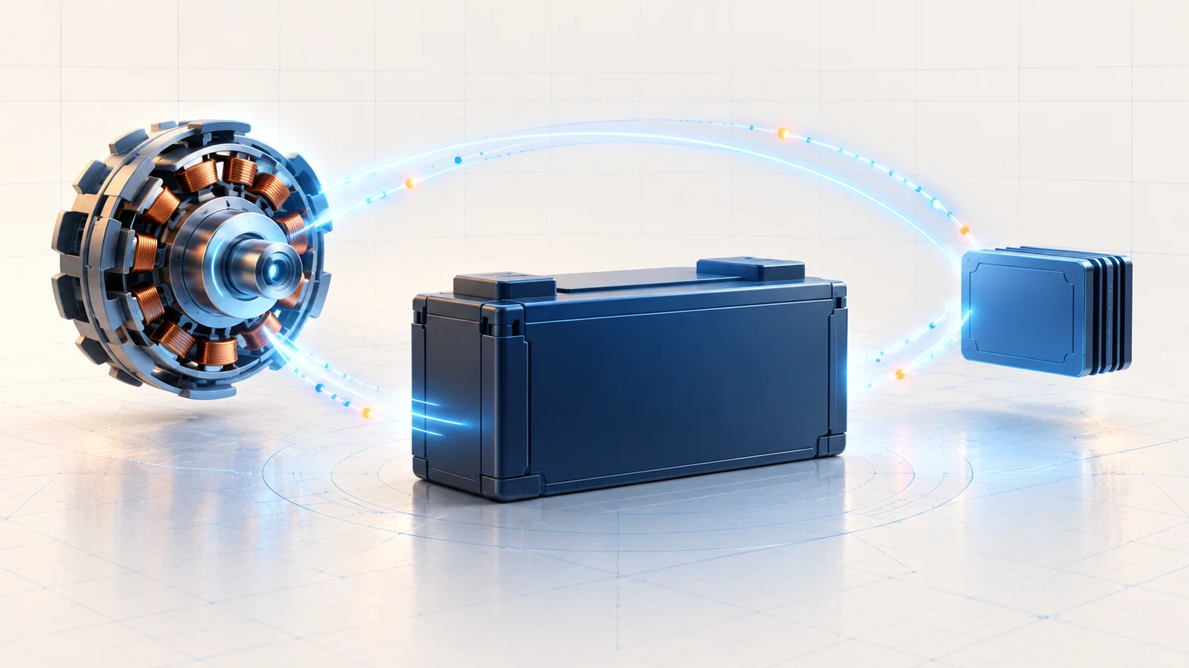
A low-voltage code is not an alternator verdict. On the Ford F-150 2.7 EcoBoost, the battery, generator, power distribution, grounds and electronic charging controls work together. A fault can affect the entire truck or only the supply reaching one module. Good diagnosis separates those possibilities before replacing parts.
This overview covers the 2015–2025 Ford F-150 2.7 EcoBoost at a conceptual level. It does not establish identical wiring, communication circuits, battery equipment or module procedures across that range. The engine is represented at both endpoints; the applicable service information for the exact year, build and equipment controls circuit identification, test conditions, voltage limits, battery service and repair verification. This is not a hybrid high-voltage system guide.
What the system does
The battery supplies energy when the engine is stopped and supports starting. With the engine running, the belt-driven generator supplies electrical loads and replenishes the battery. Power cables, fused distribution and ground paths must carry that energy without excessive loss.
Charging is also a controlled process. The powertrain control module participates in commanding and monitoring generator operation. Battery-state information and energy-management functions help the vehicle manage charging and electrical demand. Warning messages and stored faults can therefore originate from a supply problem, a control problem or the circuits connecting them.
Why running voltage is not one fixed number
Smart charging changes its target with operating conditions. Battery condition, temperature and electrical demand matter; one unloaded measurement is not a complete generator test. A changing reading is not automatically a defect, and a plausible reading at one moment does not prove the system is healthy under the conditions that produced the complaint.
The control arrangements also change. The 2015 engine-specific description uses separate generator command and monitor circuits; the 2025 description includes networked battery information and generator communication. Do not transfer a communication test, connector assignment or expected waveform from one arrangement to the other.
Energy management can reduce selected electrical loads to protect battery charge. A feature becoming unavailable may be a consequence of low available energy, not proof that the feature's own hardware failed. Likewise, some charging faults can leave the generator producing output in a fallback mode. Output alone does not prove that command, monitoring and warning functions are all operating normally.
Main failure categories
- Battery condition or state of charge: a discharged battery and a battery that cannot deliver the required performance are different findings. Establish condition with the applicable test before making a replacement decision.
- Power delivery and grounds: loose, corroded or damaged connections, cable resistance and distribution faults can prevent a module from receiving the supply available at the battery.
- Generator and mechanical drive: generator performance and the belt-drive system belong in the investigation, but only after the complaint and test conditions are established.
- Charging control and monitoring: wiring, connectors, battery-monitoring inputs and generator communication can disrupt regulation or feedback even when some charging output remains.
- Unwanted discharge: a battery that repeatedly loses charge while parked requires an appropriate key-off investigation after battery and charging checks. Do not condemn the generator solely because the battery is flat the next morning.
Symptoms and scan-tool evidence
Depending on the fault, the driver may report slow cranking, an intermittent no-start, a charging warning, electrical resets or features being restricted. Low supply can also accompany communication, drivability or gear-selection complaints. None of those symptoms identifies a failed part by itself.
Record the operating circumstances: starting, idling with loads, driving, restarting after a stop, or returning after a long park. Preserve codes and available event data before clearing them. Identify the module reporting each code, its complete code description and whether the fault is current or historical. Compare module-reported supply with a suitable direct measurement under the same conditions rather than assuming every module sees battery-terminal voltage.
Where the STEP guides fit
The exact guide and reporting module matter more than the five-character code alone.
| STEP guide | What it contributes | Boundary |
|---|---|---|
| P0562 — system voltage low, GSM guide | Separates vehicle-wide low voltage from a gear-shift-module supply, ground or connector concern. | Its column-shift 10R80 context is configuration-specific, not a procedure for every truck in the title range or every module reporting P0562. |
| P0563 — high-voltage guide and diagnostic limitation | Introduces a possible high-voltage complaint and explicitly warns against treating module-access work as diagnosis. | Its all-terrain-control-module removal material is not a supported voltage-code test path. Do not use trim removal or module replacement to diagnose P0563. |
The engine-specific charging information identifies low- and high-system-voltage diagnostic categories separately. That does not make the linked GSM procedure interchangeable with a PCM charging test. Follow the correct module and equipment path; neither code proves that the battery, generator or module needs replacement.
A practical diagnostic strategy
- Confirm the complaint and scope. Establish battery history, recent repairs and installed electrical accessories. Scan the relevant modules and determine whether several modules share the voltage concern or only one reports it.
- Inspect safely before measuring. Look for damaged cables, loose or corroded connections, damaged terminals and a mechanical drive concern. Identify the actual battery and charging configuration before disconnecting or probing anything.
- Establish battery condition. Use the applicable battery test and charging procedure. A low state of charge needs explanation; a battery passing one check does not eliminate a connection fault or an intermittent drain.
- Compare supply at the right places. Under the prescribed operating state and load, compare battery supply, relevant scan data and supply reaching the affected circuit. Use the applicable loaded voltage-drop method to evaluate power and ground paths. A continuity check alone may miss resistance that matters under load.
- Evaluate controlled charging. Follow the year-specific diagnostic branch for generator output, command, monitoring and related codes. Interpret measured voltage with the operating state and requested charging behavior, not a universal running-voltage rule.
- Separate parked discharge from running performance. If charge loss occurs after parking, use the prescribed sleep-state and current-draw procedure. Do not wake modules repeatedly and then interpret the resulting current as their settled key-off behavior.
- Verify the repair under the original conditions. Recheck battery and charging behavior, the affected module's supply and any warnings. Clear codes only at the appropriate stage, run applicable self-tests and confirm that the complaint does not return. A cleared code alone is not repair proof.
These are diagnostic categories, not a substitute pinpoint test. Exact limits, measurement points, disconnect sequences and scan-tool actions come from the applicable service procedure.
Repair categories and safety
Repairs may involve restoring cable or ground integrity, correcting damaged terminals or distribution circuits, addressing a drive or generator fault, repairing control wiring, correcting an unwanted load, or replacing a battery that fails the required test. Replace a module only after its applicable diagnosis supports that decision. Battery-monitoring service, resets and programming requirements must be checked for the exact vehicle; they are not universal steps.
Battery circuits can deliver enough current to burn tools or start a fire. Wear appropriate eye protection, keep sparks and flames away, and use rated equipment with protected leads. Keep clear of belts, pulleys and hot components. Do not disconnect the battery with the engine running as an alternator test. Do not bridge terminals, guess a jumper connection or place a meter configured for current directly across the battery.
Use the prescribed charger and connection points for the actual battery-monitoring arrangement. Follow service instructions for isolation, battery replacement and stable power during programming; a convenient connection is not necessarily a correct one. If a road test is needed, use safe data recording or a second technician rather than watching scan data while driving.
The useful question is not simply whether voltage is low or high. It is whether the observed voltage is appropriate for the operating state, reaches the module that reported the concern, and agrees with the charging system's intended behavior.

