What the engine timing and position system does
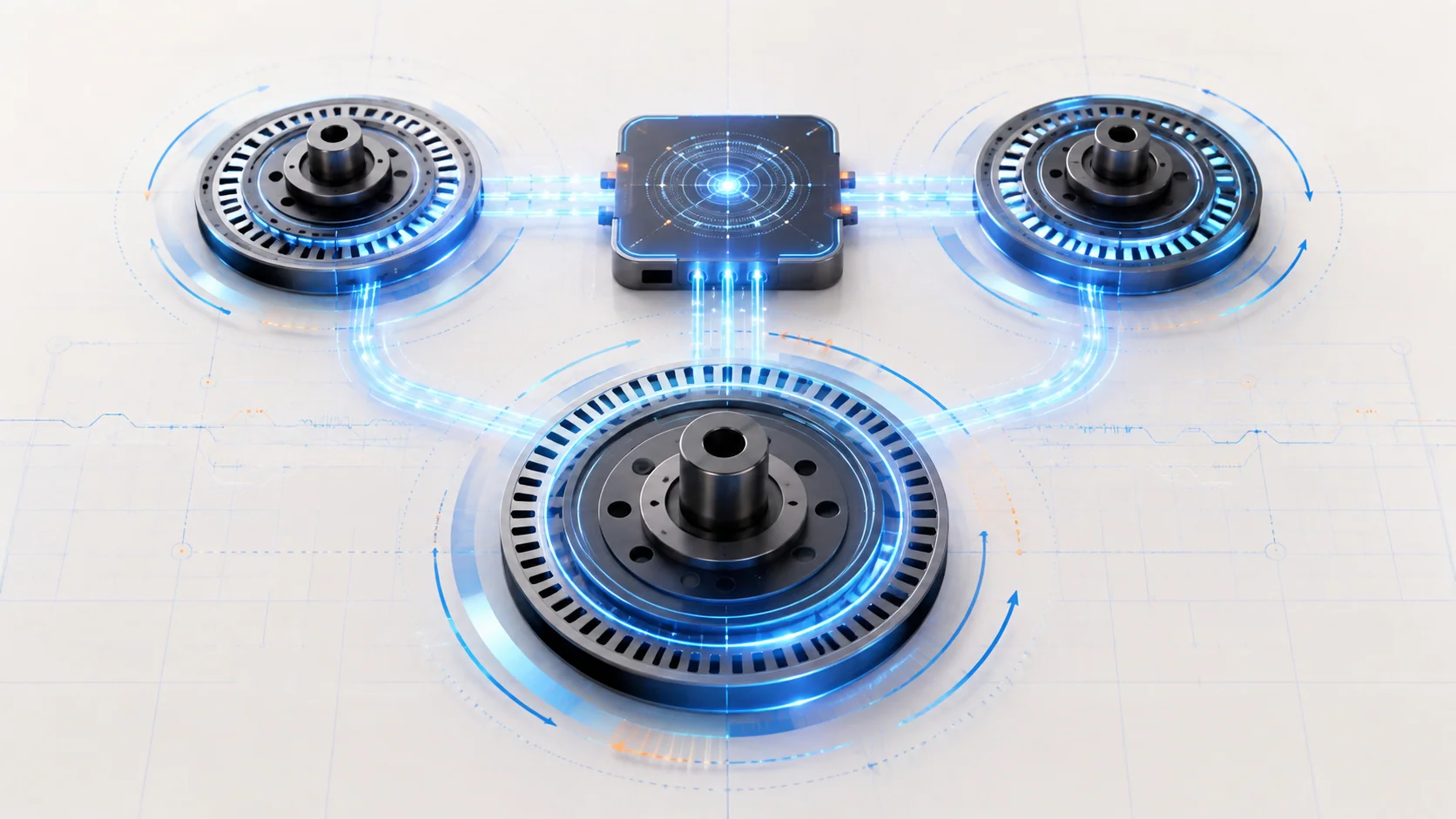
The engine control system needs an accurate reference for crankshaft speed and position, then it needs to know where the camshafts are relative to that reference. On the 3.5-liter EcoBoost, the powertrain control module (PCM) uses crankshaft-position (CKP) and camshaft-position (CMP) signals to synchronize fuel and spark control, monitor engine operation, and judge whether cam timing remains plausible.
Ford model-year material confirms that the F-150 was offered with a 3.5L EcoBoost engine throughout the 2015-2025 range. The detailed diagnostic information reviewed for this overview comes from the exact 2025 F-150 4WD 3.5L turbo application. Verify the VIN, calibration, sensor arrangement, wiring, specifications, and current service procedure for the truck being repaired. Exact hardware and procedures can differ within the grouped range.
The two related DTCs belong to the same timing-information system, but they are not the same diagnosis. P0335 reports a problem with the crankshaft-position signal path. P0340 reports a problem with one camshaft-position signal path. Neither code, by itself, proves that a sensor has failed or that the timing drive has moved.
The main functional sections
- Crankshaft reference: The CKP sensor reads a rotating trigger or pulse wheel. The resulting signal gives the PCM its primary engine-speed and crankshaft-position reference.
- Camshaft feedback: CMP sensors read targets associated with the camshafts. Their signals tell the PCM which part of the engine cycle is occurring and where each monitored camshaft is relative to the crankshaft.
- PCM synchronization: The PCM evaluates whether usable CKP and CMP signals are present and whether their relationship is credible. It also uses these inputs while controlling fuel, ignition, misfire monitoring, and variable camshaft timing (VCT).
- Mechanical timing: The timing drive keeps the crankshaft and camshafts in their base mechanical relationship. Sensor signals can be electrically healthy while a damaged, shifted, or incorrectly assembled mechanical target produces incorrect timing information.
- VCT and oil control: VCT changes cam angle during operation. Oil condition, oil pressure, control solenoids, phasers, and base timing can therefore affect cam-position behavior without causing a simple sensor-circuit failure.
- Wiring and signal integrity: Supplies, returns, signal circuits, connectors, terminal fit, harness routing, shielding where used, and electrical interference all affect whether the PCM receives a clean signal.
How the PCM builds a timing picture
During cranking, the CKP signal allows the PCM to calculate engine speed and crank position. The CMP signals add cylinder-cycle and cam-position information. Once the signals are credible, the PCM can synchronize its control functions and compare cam position with the crank reference.
The important diagnostic idea is that the PCM sees electrical patterns, not the physical parts directly. A missing pattern can come from a failed sensor, an open or shorted circuit, poor terminal contact, excessive interference, an incorrect sensor-to-target relationship, or a damaged trigger wheel. A present pattern can still be intermittent or physically misleading.
VCT adds another layer. A cam can move because the PCM commanded it through the oil-control system, or it can appear to be in the wrong place because of a signal problem, low oil pressure, a sticking control component, a phaser concern, or incorrect base timing. That is why direct CKP or CMP signal faults should be classified before a technician interprets correlation or VCT response.
Some service operations also require the PCM to learn or correct a crankshaft pulse-wheel profile used by misfire monitoring. That routine is a setup step, not a substitute for diagnosis. It cannot repair an absent CKP signal, damaged trigger wheel, poor connector, incorrect base timing, or unstable cranking condition.
What the related DTCs are telling you
| DTC | Diagnostic category | What it directs you to prove |
|---|---|---|
| P0335 | Crankshaft-position signal/circuit fault | Whether the CKP sensor, signal circuit, supply or return where applicable, connector, harness, interference, trigger wheel, sensor installation, or PCM input explains the missing or unusable crank reference |
| P0340 | Camshaft-position signal/circuit fault | Whether the applicable CMP sensor, its power, reference, return, and signal circuits as fitted, connector, harness routing, shielding or interference, sensor-to-target relationship, or PCM input explains the missing or intermittent cam signal |
P0335 is not an instruction to replace the crankshaft sensor. P0340 is not proof that the camshaft sensor is defective. Both codes describe what the PCM could not verify, so diagnosis has to prove which electrical, signal-quality, or physical-target condition caused that result. Broader oil-pressure, VCT, phaser, base-timing, or correlation branches belong later, when companion codes or individually credible but incorrectly related CKP and CMP signals justify them—not merely because P0340 is stored.
What the driver or technician may notice
Possible observations include:
- a malfunction indicator lamp with few other symptoms;
- extended cranking, a no-start, stalling, or loss of synchronization when a critical crank reference is unavailable;
- rough running, hesitation, reduced power, or inconsistent operation when a cam signal is missing or unstable;
- an intermittent fault that appears with heat, vibration, harness movement, engine speed, or electrical load;
- engine-speed data that is absent or unstable during cranking;
- synchronization or cam-position data that does not become credible;
- companion CKP, CMP, VCT, correlation, oil-pressure, misfire, supply-voltage, or communication codes;
- a concern that began after sensor, timing, engine, battery, PCM, or harness work.
These observations do not identify the failed part. Starting-system voltage, mechanical timing, oil-system condition, ignition, fuel, airflow, or network faults can create overlapping symptoms.
Safety before signal and timing diagnosis
Cranking and running tests place the technician near belts, pulleys, the cooling fan, hot turbocharger and exhaust surfaces, and moving engine components. Secure clothing, hair, tools, and test leads. Keep hands clear of rotating parts, and remember that an electric cooling fan can start unexpectedly.
Use terminal-safe probes and the exact wiring information for the truck. Do not pierce insulation, improvise a jumper, apply battery voltage to a position-sensor circuit, or disconnect a PCM connector with the system powered unless the current procedure specifically directs it. A wrong connection can damage a sensor or module and create a second fault.
Mechanical timing, trigger-wheel, phaser, and sensor service may require controlled engine positioning, special tools, one-time fasteners, and removal of hot, pressurized, fuel, oil, coolant, intake, or turbocharger-related parts. Allow the engine to cool, isolate energy as directed, support the vehicle and engine correctly, and follow current service information.
Treat any crankshaft-profile correction or other scan-tool routine as a controlled service procedure. Secure the vehicle, maintain battery condition, satisfy every enable condition, and stop if the work area or engine behavior becomes unsafe.
Common failure categories
1. The CKP or CMP circuit cannot carry a usable signal
An open circuit, short, excessive resistance, poor terminal fit, corrosion, damaged connector, failed sensor, or PCM input concern can remove or distort the signal. Prove circuit integrity under the condition that produced the fault; a static check can miss heat-, vibration-, or load-related failures.
2. Harness routing or electrical interference corrupts the signal
Position signals can be affected by chafing, altered routing, damaged shielding where used, loose grounds, poor connector retention, or interference from another electrical system. Inspect recent repair areas and compare signal behavior with vibration or controlled harness movement only when it can be done safely.
3. The sensor cannot read its physical target correctly
Incorrect sensor installation, contamination, excessive clearance, a damaged or shifted trigger wheel, or another target relationship problem can make a healthy circuit produce unusable information. A new sensor will not correct a damaged target or installation error.
4. Base timing or VCT changes cam position unexpectedly
Incorrect base timing, timing-drive movement, a phaser concern, restricted oil flow, unsuitable oil, low oil pressure, or a VCT control problem can change the cam-to-crank relationship. Investigate these broader branches when related timing, VCT, or correlation codes are present, or when individually credible CKP and CMP signals have an incorrect relationship—not merely because the direct CMP circuit passes.
5. A shared operating condition misleads the diagnosis
Low battery voltage, slow or irregular cranking, charging-system noise, poor grounds, PCM power problems, or multiple related DTCs can affect more than one signal. Stabilize shared conditions before replacing multiple components.
6. A required learned profile is absent after service
A crankshaft-profile correction may be required after specified repairs or setup events. Perform it only after the CKP signal, trigger wheel, starting system, and mechanical condition are credible. Repeating a failed routine is not a repair strategy.
A practical system-first diagnostic strategy
Step 1: Confirm the application and preserve evidence
Verify the VIN, engine, calibration, recent repairs, battery condition, and applicable Ford procedure. Save confirmed, pending, and history DTCs plus freeze-frame or failure-record data before clearing anything. Record whether the engine cranks, starts, stalls, runs rough, or loses power and whether the concern followed sensor, timing, battery, PCM, or harness work.
Step 2: Classify and prioritize the full code set
Separate direct CKP/CMP signal faults from VCT control, VCT performance, correlation, oil-pressure, supply-voltage, communication, and learned-profile faults. Follow current related-code priorities. A direct position-signal fault can make correlation or VCT data secondary because the PCM cannot judge timing reliably from an unusable input.
Step 3: Check shared basics
Confirm battery state and cranking performance, PCM power and grounds, engine oil level and condition, and obvious base-engine problems. If the engine cranks but scan data shows no credible engine speed, stay with the CKP path. If engine speed is credible but the applicable cam signal or synchronization is not, focus the CMP path without assuming that the sensor itself has failed.
Step 4: Inspect the system without erasing intermittent evidence
With the engine safely off, inspect sensor seating, connectors, locks, terminal condition, harness routing, heat exposure, chafe points, oil intrusion, grounds, shielding where used, and recently disturbed areas. Document connector position before disconnecting it. Look for physical damage only where the current procedure permits access.
Step 5: Use scan data and signal testing to answer one question at a time
Use the exact Ford procedure and equipment for the truck. Determine whether engine-speed data is stable during cranking, whether cam information is present, and whether synchronization becomes credible. When directed, use appropriate signal testing to distinguish a missing supply or return, a circuit fault, an intermittent/noisy waveform, and a physically incorrect target pattern.
Do not treat one good resistance or voltage reading as proof of signal quality. Do not compare a captured pattern with a generic example unless the engine, sensor, test point, time base, and operating condition match.
Step 6: Separate electrical, target, and mechanical branches
If the signal circuit fails, repair the proven wiring, terminal, connector, sensor, or control-side problem. If the circuit is intact but the pattern is absent or distorted, inspect sensor installation and the physical target as directed. If CKP and CMP signals are individually credible but their relationship is wrong, follow the applicable base-timing, VCT, phaser, oil-pressure, and mechanical checks.
Step 7: Perform setup only when prerequisites are credible
Complete a crankshaft-profile correction, relearn, programming, or other setup routine only when directed after the underlying signal and mechanical condition are sound. A routine that will not complete is evidence to diagnose, not a reason to repeat it indefinitely or replace the PCM without completing the directed branches.
Step 8: Verify the complete repair
Reconnect and secure every disturbed sensor, connector, shield, retainer, ground, intake connection, fluid connection, and mechanical fastener. Clear codes when directed, perform required setup, repeat the self-test, reproduce the original operating condition, and confirm stable engine-speed, cam-position, and synchronization data. Check that no related pending DTC returns.
A warning light that remains off immediately after clearing codes is not repair verification.
Match the repair to the proven failure
The supported repair may be a terminal or harness repair, corrected routing or shielding, restored power or ground, corrected sensor installation, sensor replacement, target or trigger-wheel repair, restored oil pressure or flow, VCT control repair, phaser or timing-drive service, completion of an authorized setup routine, or—only after the directed diagnosis supports it—PCM repair or replacement with required programming.
Avoid common shortcuts:
- replacing the CKP sensor for every P0335 without checking the circuit and trigger wheel;
- replacing the CMP sensor for every P0340 without first checking the direct signal path, connector, routing or interference, and sensor-to-target condition; investigate oil pressure, VCT, phasers, or base timing only when companion codes or credible but incorrectly related CKP and CMP signals justify those branches;
- calling either code proof of a jumped timing drive;
- using a profile correction to hide a bad signal or damaged target;
- condemning the PCM before connectors, circuits, signals, and physical relationships are proved;
- clearing codes before saving the conditions that made the fault appear.
The takeaway
The CKP and CMP systems give the PCM two different parts of the engine-timing picture. P0335 asks whether the crankshaft reference is usable. P0340 asks whether a specific camshaft-position signal is usable. Diagnose the full code set, stabilize shared operating conditions, prove circuit and signal quality, inspect the physical target, and only then move into base timing, VCT, or module branches.
That order turns a broad timing complaint into a controlled evidence chain and prevents a sensor code from becoming an unsupported sensor replacement.