What this code means
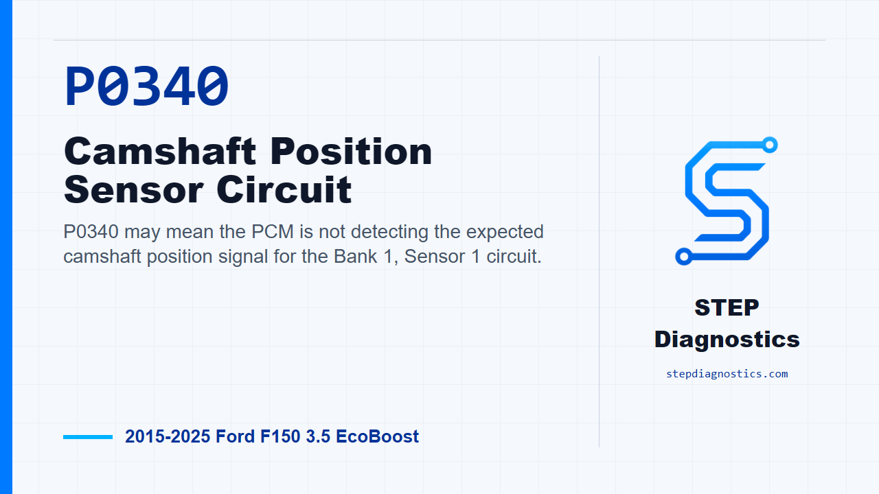
P0340 may mean the PCM is not detecting the expected camshaft position signal for the Bank 1, Sensor 1 circuit.
What the vehicle may do
- The vehicle may have a no-start condition.
- The engine may run with cam sync or cam timing related symptoms.
- The concern can be intermittent, especially when wiring, connector condition, or electrical noise is involved.
Possible fault areas
- Possible CMP sensor circuit or connector concern.
- Possible electrical interference, generator noise, or related signal issue.
- Possible base-engine oil pressure, engine timing, or VCT-related condition affecting cam position.
Diagnostic path
Opening and diagnostic frame
On this 2015 to 2025 Ford F-150 with the 3.5 EcoBoost, P0340 points to a camshaft position sensor circuit concern. In plain terms, the PCM may not be seeing the Bank 1, Sensor 1 cam signal the way it expects. The truck may have a no-start, it may run with cam timing or sync complaints, or the code may come back intermittently. Broadly, think in three buckets: the CMP sensor and its wiring, electrical interference or power and reference circuit issues, and possible base-engine or VCT-related conditions that can affect cam position. Start with the basic system checks, then follow a structured diagnostic approach instead of jumping straight to a sensor.
Confirm the code path
First, check for codes. For this episode, we are focused on P0340, but if other cam sensor or cam timing related codes are present, use them as context for which CMP sensor and circuit the PCM is complaining about. If the vehicle is a no-crank or no-start with this CMP code present, move directly to checking voltage at the suspect CMP sensor. For the normal diagnostic path, continue with the harness inspection. If the CMP code is not present and you are chasing symptoms only, pause this code path and follow the symptom-based diagnostic direction instead.
Inspect the harness before testing deeper
With the ignition off, inspect the harness before you start back-probing or condemning anything. Look at routing, alterations, shielding issues, and anything that could let another system induce noise into the cam signal. Also inspect the CMP connector for damage or corrosion. If you find a harness or connector concern, repair it as needed, clear the PCM codes, and repeat the self-test. If the harness and connector check clean, move on and try to make the code return.
Reproduce the fault
Next, clear the code and attempt to retrieve it. Turn the ignition on, start the engine, raise engine speed to greater than 1,500 RPM for 10 seconds, and repeat that 3 times. If the CMP code returns, keep going down this electrical path. If it does not return, do not force a conclusion. Consider that ignition system noise, alternator noise, radio frequency interference, or crank sensor concerns can affect this type of signal. On a VCT engine, also keep oil level, oil filter condition, oil contamination, and VCT system concerns in mind because they can create cam positioning errors.
Check for generator electrical noise
If the code comes back, check the generator for excessive electrical noise. Start the engine and listen for audible electric noise from the generator. Then shut the ignition off, disconnect the generator or regulator B+ connector, restart the engine, and listen for whether the noise stays steady, decreases, or increases. If the noise stays steady with the B+ connector disconnected, continue to the CMP sensor voltage check. If the noise does not stay steady, diagnose the charging system noise before continuing with the CMP circuit path.
Check voltage at the suspect CMP sensor
Now test the suspect CMP sensor indicated by P0340. With the ignition off, reconnect the generator or regulator B+ connector, disconnect the CMP sensor connector, then turn the ignition on. On the 3.5 EcoBoost, measure the CMP sensor voltage at the appropriate connector for the suspect sensor. The path continues if the VBPWR circuit is greater than 10.5 V, or if the VREF circuit is between 4.5 and 5.5 V. If the voltage is not in the expected range for the circuit being tested, stop this CMP signal path and diagnose that power or reference circuit issue first.
Check for opens in the CMP circuits
If the voltage check passes, leave the suspect CMP sensor path and check the CMP circuits for an open. Disconnect the PCM connector and measure resistance through the listed CMP signal and return circuits for the suspect sensor. The resistance should be less than 5 Ω. If it is, continue to the short check. If it is not less than 5 Ω, repair the open circuit, clear the PCM codes, and repeat the self-test.
Check for shorts in the CMP circuits
Next, check the CMP circuit for a short. Measure resistance between the listed CMP circuit lead pairs for the suspect sensor. The resistance should be greater than 10K ohms. If the resistance is greater than 10K ohms, continue to the short-to-voltage check. If it is not greater than 10K ohms, repair the short circuit, clear the PCM codes, and repeat the self-test. For any pin pairing that is not clear during this short check, pause and recheck the earlier diagnostic path rather than guessing at the measurement.
Check for short to voltage
Then check the CMP circuit for a short to voltage. With the ignition on, check the listed CMP signal leads for voltage at the suspect sensor circuit. If any voltage is present where this check is being made, repair the short circuit, clear the PCM codes, and repeat the self-test. If no voltage is present, reconnect the CMP sensor and PCM and move to the operating check. If the matching test lead for this voltage check is not clear, do not improvise the hookup; pause and recheck the diagnostic path before continuing.
Check CMP sensor operation
With the ignition off, connect the CMP sensor connector and the PCM connector. Start the engine, access the PCM data, and monitor the SYNC PID. If the engine starts and SYNC reads YES, go to the final code check. If the engine does not start, or SYNC does not read YES, the supported next move in this path is to install a new Camshaft Position sensor, clear the PCM codes, and repeat the self-test.
Verify the repair and confirm the code stays gone
Keep verification separate from the circuit testing. After the operating check, check for codes again. If any codes are present at this point, this path supports installing a new Camshaft Position sensor, clearing the PCM codes, and repeating the self-test. If no codes are present, the system is operating correctly at this time. The concern may have been caused by a loose or corroded connector. Clear the PCM codes and repeat the self-test to confirm the code stays gone.
Takeaway
The key on P0340 is to prove the signal path before calling the sensor: confirm the code, inspect the harness, reproduce the fault, rule out electrical noise, verify the CMP power or reference circuit, then check for opens, shorts, and sync operation. For more diagnostic training, visit stepdiagnostics.com.
Final check
P0340 is best approached by proving the CMP signal circuit and operating sync before making a repair decision.
For more guided automotive diagnostics, visit STEP Diagnostics.