What the system is trying to control
The 3.5-liter EcoBoost engine depends on a closed control loop. The powertrain control module (PCM) calculates how much fuel the engine should receive, watches the exhaust sensors to see what combustion produced, corrects fuel delivery when needed, and separately evaluates whether the catalytic converter is storing oxygen and treating exhaust gases as expected.
Ford model-year material confirms that the F-150 was offered with a 3.5L EcoBoost engine throughout the 2015-2025 range. The detailed operating and diagnostic information reviewed for this overview comes from the exact 2025 F-150 4WD 3.5L turbo application. Verify the VIN, calibration, sensor layout, wiring, specifications, and current service procedure for the truck being repaired. Exact hardware and monitor conditions can differ within the grouped range.
The related DTCs describe different failed behaviors. P0053 concerns the heater circuit for the upstream bank 1 oxygen sensor. P0171 reports that bank 1 adaptive correction reached its calibrated rich limit while responding to a lean condition. P0420 reports that the bank 1 catalyst monitor calculated efficiency below its threshold. None of these codes, by itself, proves which part has failed.
The main functional sections
- Air and fuel calculation: The PCM uses airflow, pressure, temperature, engine speed, load, and operating-state information to calculate a base fuel command.
- Upstream oxygen feedback: The upstream sensor responds to the oxygen content associated with combustion. Its signal is a primary input for closed-loop mixture correction after the sensor is ready.
- Sensor heating: A controlled heater helps the oxygen sensor reach and maintain its working temperature. Heater performance and signal performance are related, but they are not the same diagnostic category.
- Short- and long-term correction: The PCM makes immediate corrections and learns longer-term adjustments. Fuel trim shows what the controller is doing to reach its mixture target; it does not identify the cause of the correction.
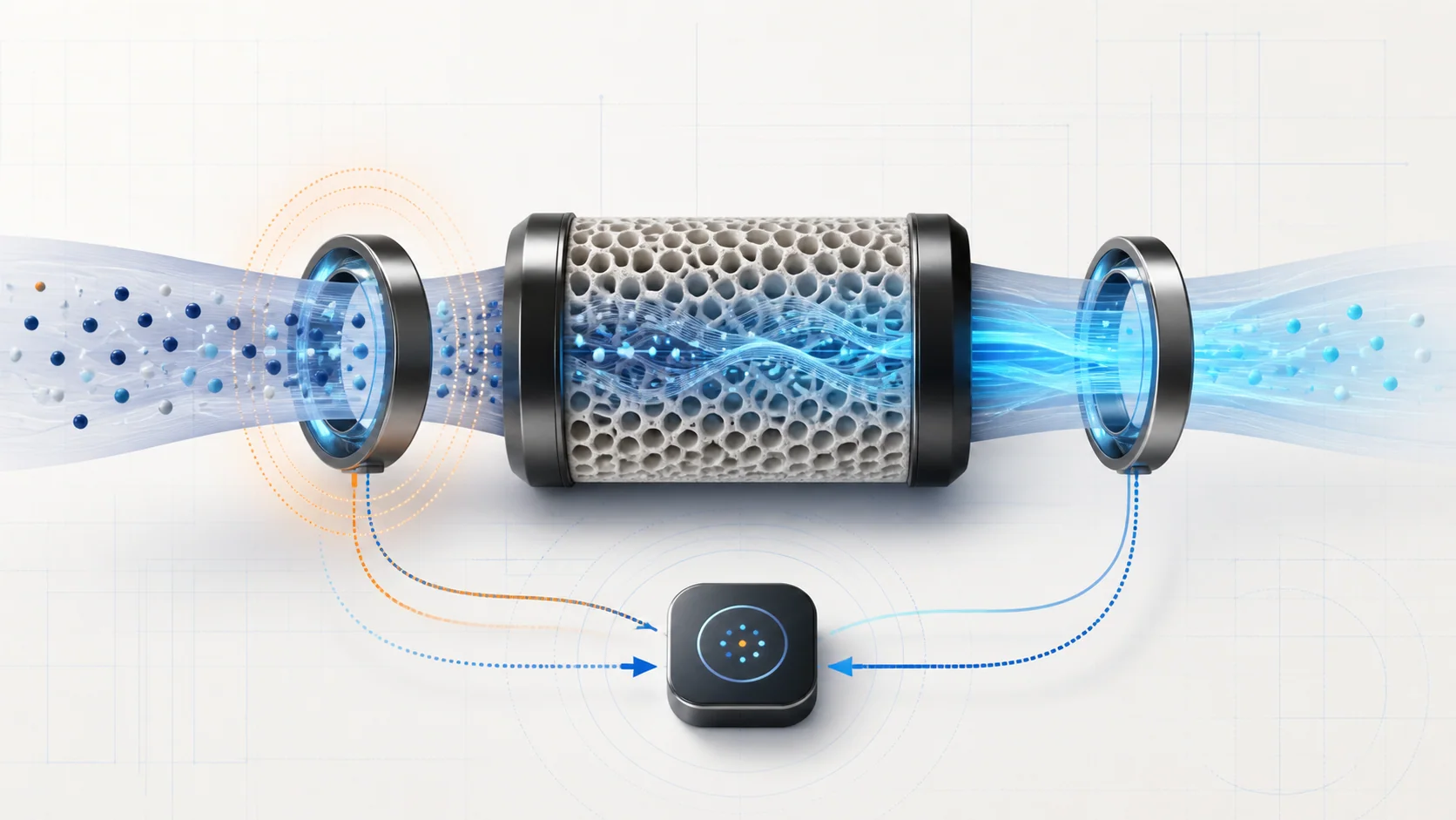
- Catalytic conversion: The catalyst treats exhaust gases and stores/releases oxygen as operating conditions change. Its performance depends on correct engine operation and an exhaust path without misleading leaks.
- Downstream monitoring: The downstream sensor gives the PCM evidence about oxygen behavior after the catalyst. The PCM compares patterns over a qualifying operating period rather than judging the converter from one voltage snapshot.
How the feedback loop and catalyst monitor connect
The PCM begins with a calculated fuel command. Once the upstream sensor is ready and operating conditions allow closed-loop control, the controller adjusts fuel delivery according to exhaust feedback. Short-term fuel trim shows the immediate response; long-term fuel trim represents learned correction retained for recurring conditions.
If unmetered air enters the engine, fuel supply is inadequate, an injector contributes incorrectly, purge flow is excessive, an exhaust leak changes sensor exposure, or a sensor reports biased information, the PCM may add fuel. P0171 is stored when the bank 1 adaptive correction reaches the applicable limit. That is a control result—not proof that the oxygen sensor is bad and not proof that the fuel pump is weak.
The catalyst monitor uses different evidence. A healthy catalyst buffers changes in oxygen content, so downstream activity should show the effect of that storage and conversion. As the catalyst loses oxygen-storage capacity, its downstream pattern can become less distinct from upstream activity. The PCM evaluates that behavior only when enabling conditions are satisfied.
These functions are connected because the catalyst cannot be judged fairly when the engine is misfiring, the mixture is persistently incorrect, a sensor heater or signal circuit is faulty, or the exhaust leaks. Repair upstream control problems first, then run the applicable monitor and assess the catalyst with clean evidence.
What the related DTCs are telling you
| DTC | Diagnostic category | What it directs you to prove |
|---|---|---|
| P0053 | Bank 1 sensor 1 heater resistance/current | Whether the heater element, power and control paths, connector, wiring, or PCM control explains the electrical result |
| P0171 | Bank 1 system too lean | Why the PCM had to add excessive fuel: real excess air, inadequate fuel, purge/PCV flow, exhaust leakage, combustion trouble, or biased measurement |
| P0420 | Bank 1 catalyst efficiency below threshold | Whether related engine faults, contamination, exhaust leaks, sensor/circuit problems, or a degraded catalyst explain the failed monitor |
P0053 is not an instruction to replace the upstream sensor. P0171 is not a parts list. P0420 is not automatic authorization for a catalytic converter. Each code identifies the next category of evidence to collect.
What the driver or technician may notice
Possible observations include:
- a malfunction indicator lamp with little immediate change in drivability;
- rough idle, hesitation, surge, reduced power, or hard starting when the mixture problem is large enough;
- positive fuel correction concentrated at idle, under load, or during a particular temperature range;
- slow entry into closed-loop operation or a heater code after a cold start;
- misfire, airflow, purge, fuel-pressure, injector, or oxygen-sensor codes accompanying P0171 or P0420;
- exhaust noise, odor, soot marks, damaged wiring, or heat-related connector trouble;
- a catalyst monitor that may remain incomplete while prerequisite faults are active or enabling conditions are not satisfied;
- a recurring P0420 after an upstream engine, oil-consumption, or fueling problem has already damaged or contaminated the catalyst.
Symptoms help reproduce the condition but do not identify the failed component. A lean indication can be real or sensor-biased, and a catalyst-efficiency result can be caused or distorted by problems outside the converter.
Safety before testing
Allow the turbocharger, exhaust manifolds, oxygen sensors, pipes, and catalytic converter to cool before touching them. Exhaust components can remain hot long after the engine is switched off. Work in a ventilated area and route exhaust outdoors when the engine must run. Never work in an enclosed space where carbon monoxide can accumulate.
Support the truck correctly if access underneath is required. Keep wiring, test leads, clothing, and hands away from belts, fans, hot exhaust parts, and moving driveline components. Do not pierce insulation, spread terminals, improvise heater jumpers, or apply battery voltage directly to an oxygen-sensor circuit. Use terminal-safe probes and the current wiring information.
Fuel-pressure or injector tests introduce gasoline hazards even though the initial complaint concerns exhaust feedback. Follow the exact pressure-relief procedure, contain released fuel, and keep sparks and flame away. Do not use flammable sprays to search for intake leaks. Stop testing if a fuel or exhaust leak creates an unsafe condition.
Common failure categories
1. Heater power, control, or element fault
An open heater, damaged wiring, poor terminal fit, corrosion, a power-supply fault, a control-circuit problem, or PCM driver concern can produce P0053. Prove the circuit under the applicable conditions before replacing the sensor. A heater problem can delay sensor readiness, but it does not automatically prove the sensing element is inaccurate.
2. Unmetered air or unintended vapor flow
Leaks in intake plumbing, vacuum connections, PCV paths, brake-booster plumbing, manifold sealing, or purge control can add air or vapor outside the intended calculation. Idle-sensitive correction often suggests a different branch from a concern that appears only at high load, but the recorded operating condition must guide the test.
3. Fuel delivery or injector contribution problem
Low supply, pressure-control trouble, restricted flow, poor fuel quality, or an injector that contributes too little can force the PCM to add fuel. Do not condemn a pump from fuel trim alone. Confirm pressure, volume, command, feedback, and cylinder contribution with the exact procedure.
4. Biased air or exhaust measurement
An airflow, pressure, temperature, or oxygen-sensor signal can remain electrically plausible while being inaccurate. Compare related inputs, bank behavior, operating conditions, and known-good expectations. An oxygen sensor should be replaced only when circuit and response evidence identifies it.
5. Exhaust leakage or sensor-installation problem
An exhaust leak can expose a sensor to outside oxygen and distort fuel-control or catalyst-monitor evidence. Check the path around the sensors and catalyst, connector identity, harness routing, and prior repair work. Repair leaks before interpreting catalyst efficiency.
6. Combustion, oil-consumption, or catalyst damage
Misfire, incorrect mixture, injector trouble, base-engine faults, turbocharger-related concerns, or sustained oil contamination can overheat, poison, or physically damage a catalyst. Correct the upstream cause before installing a converter; otherwise the replacement may fail again.
A practical diagnostic sequence
1. Preserve the evidence
Scan all modules before clearing codes. Save freeze-frame or snapshot data, code status, fuel trims, sensor and heater information, airflow/load data, misfire evidence, temperatures, and system voltage. Record recent exhaust, turbocharger, intake, fuel, engine, calibration, or wiring work.
2. Establish code priority
Address low voltage, communication faults, shared-power or reference faults, misfire, direct heater/sensor circuit codes, and obvious air, fuel, or exhaust faults before judging a catalyst monitor. Follow the current service-information priority when several codes are present.
3. Inspect the complete path
Check intake ducts and connections, vacuum/PCV/purge plumbing, electrical connectors, harness heat damage, exhaust sealing, sensor installation, and signs of fuel or oil contamination. Visual findings must be confirmed rather than used as a guess.
4. Separate electrical readiness from mixture accuracy
For P0053, test the heater circuit as an electrical system. Confirm power, control, wiring, connector condition, and heater response before deciding on a sensor or controller. After repair, confirm that the sensor becomes ready normally.
5. Decide whether the lean result is real
For P0171, compare bank behavior and correction at the recorded load and temperature. Determine whether the evidence points toward unmetered air, vapor flow, inadequate fuel, cylinder contribution, exhaust leakage, or biased measurement. Fuel trim is the starting observation, not the final diagnosis.
6. Protect the catalyst decision
Before condemning the converter for P0420, repair related heater, sensor, mixture, misfire, injector, engine, oil-consumption, turbocharger, and exhaust-leak concerns. Confirm the correct upstream and downstream sensor connections and credible signals. A single downstream voltage or a generic temperature comparison is not a complete catalyst test.
7. Reproduce and verify
Reproduce the stored operating condition safely. After correcting the proven cause, clear codes or learned values only when instructed, run the applicable self-test or qualifying drive, and confirm that fuel correction, sensor readiness, and catalyst-monitor status are normal. Re-scan all modules and make sure no new fault was introduced.
Repair direction by confirmed cause
- Repair heater power, control, wiring, connector, or terminal faults before replacing an oxygen sensor.
- Repair intake, PCV, purge, or exhaust leaks and then reassess fuel trim and monitor evidence.
- Correct fuel-pressure, injector-contribution, ignition, compression, timing, or measurement faults identified by directed testing.
- Address oil consumption, contamination, misfire, or persistent mixture faults before catalyst replacement.
- Replace an oxygen sensor only when its heater, circuit, or response fails the applicable test.
- Replace a catalytic converter only after upstream causes, leaks, sensor identity, signal credibility, and enabling conditions have been proven.
The key takeaway
Think of this as two connected control tasks. The PCM first uses upstream oxygen feedback and learned correction to control mixture; it then uses downstream evidence to evaluate the catalyst. P0053 asks why an upstream heater circuit did not behave correctly. P0171 asks why bank 1 adaptive correction reached its calibrated rich limit while responding to a lean condition. P0420 asks why the catalyst monitor did not see the expected oxygen-storage behavior. Diagnosing those questions in order—electrical integrity, air and fuel control, combustion and exhaust integrity, then catalyst performance—prevents unnecessary sensor and converter replacement.