What this code means
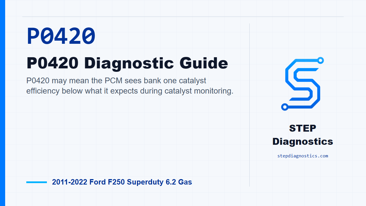
P0420 may mean the PCM sees bank one catalyst efficiency below what it expects during catalyst monitoring.
What the vehicle may do
- The check engine light may be on.
- The vehicle may fail an emissions test.
- Driveability may often seem normal.
- Other upstream engine or fuel-control symptoms may be present.
Possible fault areas
- Possible oxygen sensor circuit or connector concerns.
- Possible exhaust leak or exhaust system concern.
- Possible fuel pressure, fuel control, or injector concern.
- Possible base engine, misfire, oil consumption, or contaminated oil concern.
- Possible catalyst deterioration.
Diagnostic path
Open on what P0420 is really telling you
On this 2011 to 2022 Ford F-250 Super Duty with the 6.2 gas engine, P0420 means the PCM may be seeing bank one catalyst efficiency below the acceptable threshold. Under normal closed-loop fuel control, a healthy catalyst stores oxygen; as catalyst efficiency drops, that oxygen storage ability drops with it. The truck may only have a check engine light, it may fail an emissions test, or it may have other symptoms if the problem is upstream. So don’t jump straight to the converter. Possible fault areas can include HO2S circuitry or connectors, exhaust system concerns, contaminated oil, base engine operation, fuel injector concerns, the oxygen sensors, and the catalyst itself. Internal converter deterioration is usually caused by abnormal engine operation upstream of the catalyst, and misfiring is especially suspect. Also ask about high oil consumption, because heavy oil consumption can deposit phosphorus on the catalyst and reduce efficiency.
If it came in from an emissions failure, start with the report
If this truck is here because it failed an inspection or maintenance test, analyze the report before touching parts. Check for data entry problems like model, model year, calibration if it is listed, and test weight if it is listed. Then look at the gas readings, identify which gases are high or low, and if the report includes a drive cycle, note the mode where the gases failed. Make sure the engine and catalyst were warm and stabilized before the test, and watch for excessive idling before the test. The example math matters when you are comparing a failed result to a baseline: the actual HC produced by a vehicle is 1.6 gpm, the cutpoint for HC in this example is 0.8 gpm, the HC reading during the baseline drive averages 440 ppm, and the verification trip must show at least half of the baseline reading, or an average of 220 ppm or less. If the vehicle failed only an EVAP leak or purge flow test, set the catalyst path aside and treat it as an EVAP-only concern. If not, baseline the vehicle with an exhaust gas analyzer, using the same repeatable drive if it has to be driven, and watch for driveability, shifting, or exhaust smoke symptoms. Then check for obvious symptoms, do the preliminary checks on vacuum lines, electrical connections, scheduled maintenance, installed emissions equipment, and the intake air path, and run the PCM self-test to see whether any other PCM codes need to be handled first.
Use the gas readings to decide which upstream system to chase
Once the baseline is done, use the gases to decide the next move. If carbon monoxide is excessive, treat that as a rich-running clue, then check whether HC is also excessive. With high CO and high HC, look for rich operation and incomplete combustion first: secondary ignition, fuel delivery concerns such as high fuel pressure or poor pressure hold, vacuum leaks or restrictions in the PCV system, exhaust system concerns, and base engine concerns. If HC is excessive while CO is low to normal, treat that as a lean-running clue and work through fuel delivery, secondary ignition, PCV or vacuum issues, and base engine concerns such as intake manifold leaks, incorrect compression, or valvetrain or camshaft damage. If NOx is excessive with normal to low HC and CO, move toward base engine causes such as excessive carbon buildup in the combustion chamber, then check torque converter clutch operation, cooling system airflow concerns, intake air modifications, and lean-running causes like vacuum leaks or low fuel pressure. If a branch does not prove a concern, keep moving through the ordered checks instead of guessing at the converter.
Handle an EVAP-only branch separately
If the only verified concern is EVAP-related, analyze when that concern is present and try to verify it. Check the fuel filler cap if equipped, the capless filler pipe if equipped, EVAP lines and hoses for correct connection, restriction, or damage, and the fuel vapor storage canister for damage. Then run the PCM self-test, and if needed, check the EVAP system for leaks. After an EVAP repair, verify the repair separately: reset KAM to reset readiness, relearn the basic adaptive values by running the engine at 2,500 RPM for 1 minute and idling the engine for 2 minutes, run the PCM self-test again, and carry out the EVAP leak test and flow check. If it passes, that EVAP branch is done. If it does not pass, the original concern was not repaired or another concern is still present.
Keep verification separate from catalyst testing
For a non-EVAP emissions repair, verify the repair before making the final catalyst call. Confirm the repair, reset KAM to reset readiness, and relearn the basic adaptive values by running the engine at 2,500 RPM for 1 minute and idling the engine for 2 minutes. Then run the PCM self-test, handle any other codes, and repeat the exhaust gas analyzer baseline. If the vehicle needs to be driven first, it may need to be driven up to 8 km (5 miles), and the same drive mode used for the original baseline should be used. If all gases are within the acceptable range, the repair is verified. If not, go back to the beginning of the emissions path because the gas level is still high or another gas is now above the acceptable range. Only after the previous testing is complete, use the catalyst delta temperature test: run the engine for 2 minutes at 2,500 RPM to heat the exhaust system, turn the ignition off, disable one cylinder bank at a time as directed for the ignition type, then run the engine at approximately 1,000 RPM. Measure the inlet and outlet surface temperature of each catalytic converter and compare the readings. More than 28°C (50°F) between inlet and outlet means that converter is operating correctly. If a converter is less than that, repeat the test; if it is still less than required, install a new catalytic converter and verify the repair.
Now confirm this is the P0420 code path
For the P0420 diagnostic path, first confirm the catalyst efficiency code is actually present. The same test area also covers the matching concern on the other bank, but this episode stays on bank one. If other codes are present besides the catalyst efficiency codes, check what they mean first, clear the PCM codes, and repeat the self-test before continuing. That matters because misfire, fuel control, sensor, or base engine problems can damage a catalyst or make the monitor fail even when the converter is not the root cause.
Do not diagnose by odor alone
If the complaint includes a sulfur smell, keep it in perspective. A slight sulfur smell may be normal, especially on a new vehicle or a new catalyst with less than 8,000-16,000 kilometers (5,000-10,000 miles). Installing a new catalyst can actually make that symptom worse. Use the monitor and the upstream checks, not odor alone, to make the catalyst decision.
Check the wiring before chasing the converter
Next, inspect the electronic engine control harness. Look closely at the HO2S connectors for crossed wiring, and inspect the harness for exposed wiring, corrosion, and correct routing. Also inspect the PCM connectors for damaged pins, pushed-out pins, corrosion, and loose wires. If the rear oxygen sensor connections are crossed, the catalyst efficiency monitor can fail. If you find a wiring or PCM connector concern, repair it as needed, clear the PCM codes, and run the catalyst monitor drive cycle to verify the repair.
Verify fuel pressure and FRP sensor behavior
After the wiring check passes, check fuel pressure. With ignition on, use the FLP pressure PID where that applies. On a mechanical returnless fuel system, turn the ignition off, relieve fuel pressure, connect a mechanical fuel pressure gauge, pressurize the system by cycling the ignition, and compare the reading to the fuel system specification for that test path. Be careful here: the fuel system remains pressurized when the engine is not running. Fuel pressure above specification can create an abnormally rich mixture and raise catalyst temperature. Also remember that all PIDs may not be available on every vehicle. If fuel pressure is in specification, check for a biased FRP sensor by turning the ignition off, disconnecting the Fuel Injection Pump connector, starting the engine, commanding FUEL_MASS_DI to maximum, and monitoring FRP pressure. The expected FRP PID value is between 345-827 kPa (50-120 PSI). If it is not in that range, install a new Fuel Rail Pressure sensor, clear the PCM codes, and repeat the self-test. There is also an FRP-to-FLP comparison check in this same area: FRP should be within 138 kPa (20 PSI) of the FLP value. If the path into that comparison is not clear on the vehicle you’re working on, pause, recheck the earlier diagnostic path, and avoid guessing.
Pressure-test the exhaust for leaks
If the fuel checks pass, check the exhaust system for leaks. Pressurize the exhaust at the tailpipe outlet with regulated shop air, but do not overdo it. Pressure above 241 kPa (35 psi) can damage system components, so regulate the shop air to 34.4 kPa (5 psi) before connecting to the system. Use soap and water around the exhaust flanges and gaskets, the oxygen sensor mounting surfaces, the exhaust section between the upstream and rear oxygen sensors, and the exhaust system within 15.25 cm (6 inches) of the downstream HO2S and its mounting surface. Also check the exhaust flange bolts and downstream HO2S for correct torque. If you find a leak or torque concern, repair it as needed, clear the PCM codes, and run the catalyst monitor drive cycle to verify the repair.
Check for exhaust restriction when the leak check is not the answer
If the exhaust leak check does not find a concern, inspect for exhaust restrictions. Look at the front and rear exhaust pipes, catalytic converter, muffler, and tailpipe assembly for damage or restriction. Then decide whether an exhaust back pressure tester is available. If it is, install the tester and follow the tool maker’s setup and test method. A slight amount of exhaust pressure is normal, but excessive back pressure seriously affects engine operation. Typical exhaust back pressure, measured near the exhaust manifold at normal operating temperature, should not exceed 20.7 kPa (3 psi) at idle and 55.2 kPa (8 psi) at wide open throttle under load. If a back pressure tester is not available, use manifold vacuum as the restriction check. Attach a vacuum gauge to an intake manifold vacuum source and watch the gauge while raising RPM. On startup and idle, the reading may be normal 51-74 kPa (15-22 in-Hg), but a clogged exhaust can make the needle slowly drop to 0 kPa (0 in-Hg), then slowly rise. If either test indicates restriction, repair it as needed, clear the PCM codes, and repeat the self-test. If no restriction or leak indication is found, continue only with the proper symptom path and do not force a restriction diagnosis.
Use the catalyst monitor as the final decision point
If the wiring, fuel pressure, FRP sensor check, and exhaust leak check all pass, carry out the catalyst monitor drive cycle. This is the decision point for P0420. If P0420 is still present after the monitor runs, install all new catalytic converters on bank 1, clear the PCM codes, and repeat the self-test. If P0420 does not return, the test is complete and no concern is present.
Final takeaway
The main point with P0420 is to prove the converter failed the monitor after the upstream causes have been checked. Start with the emissions context when there is one, separate EVAP-only failures, baseline the gases, follow the rich, lean, or NOx clues, confirm the bank one catalyst code path, inspect the oxygen sensor wiring, verify fuel control, pressure-test the exhaust, check restriction when needed, and only then make the bank one catalyst decision. For more diagnostic training, visit stepdiagnostics.com.
Final check
P0420 can be a catalyst problem, but it should be diagnosed by checking possible upstream causes and confirming the monitor result before condemning the bank one catalyst.
For more guided automotive diagnostics, visit STEP Diagnostics.