What this code means
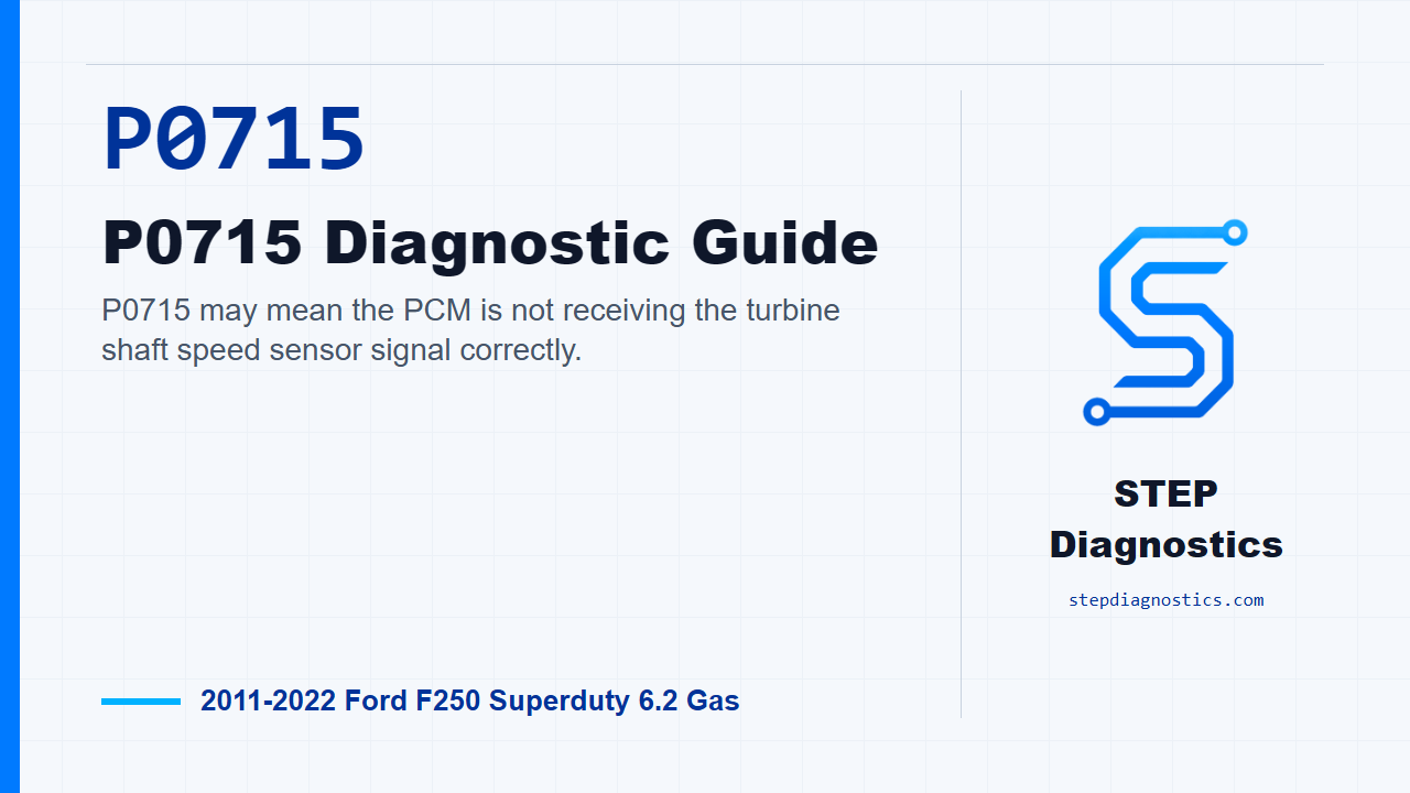
P0715 may mean the PCM is not receiving the turbine shaft speed sensor signal correctly.
What the vehicle may do
- The vehicle may show transmission shift complaints.
- A warning light may come on.
- The transmission can sometimes use a default strategy when speed information is not reliable.
Possible fault areas
- Possible TSS sensor concern.
- Possible connector, terminal, or wiring issue.
- Possible transmission case harness issue.
- Possible PCM-side circuit concern.
Diagnostic path
Opening context
On this 2011 to 2022 F-250 Super Duty with the 6.2 gas engine and 10R140 transmission, P0715 points us toward the turbine shaft speed sensor circuit. In plain language, the PCM may not be seeing the TSS signal correctly. The truck may have shift complaints, a warning light, or default-type transmission behavior when that speed information is not reliable. Possible fault areas can include the TSS sensor, connector condition, wiring integrity, terminal fit, the transmission case harness, or the PCM side of the circuit. If other transmission codes are present, check what they mean first, but for this run we’re staying focused on the P0715 TSS circuit path.
Start with the P0715 circuit direction
For P0715, treat this as an open circuit or short to ground concern in the TSS sensor circuit. This speed-sensor test is shared with other speed sensor faults, but only test the circuit tied to the code retrieved during the KOEO test. For this code, stay on the TSS side of the checks and do not chase other speed sensor branches unless their codes are actually present.
Check TSS VREF at the transmission connector
Ignition off, disconnect transmission vehicle harness connector C168A. Before measuring anything, look closely for damaged or pushed-out terminals, corrosion, loose wires, and missing or damaged seals. Then turn the ignition on and measure the TSS VREF circuit from C168A Pin 8 to ground. If the voltage is approximately 9 volts, move ahead to the signal return checks. If it is not approximately 9 volts, continue by checking that VREF circuit for a short to ground.
If VREF is missing, check short to ground and open circuit
With ignition off, disconnect PCM connector C175T. Measure C168A Pin 8 to ground. If resistance is greater than 10,000 ohms, the VREF circuit is not shorted to ground, so keep going and check for an open. If it is not greater than 10,000 ohms, repair the circuit. Next, check the TSS VREF path from C168A Pin 8 to C175T Pin 35. If resistance is less than 3 ohms, the path is intact and the next branch is the PCM guided routine. If programming is performed, carry out the transmission strategy download. At that point, pause, complete that guided routine, and avoid guessing. If resistance is not less than 3 ohms, repair the circuit.
Check the TSS signal return circuit outside the transmission
Once the VREF check sends you forward, check the TSS signal return circuit for an open. Ignition off, PCM connector C175T disconnected, measure C168A Pin 1 to C175T Pin 38. If resistance is less than 3 ohms, continue. If not, repair the circuit. Then check that same signal return for a short to ground by measuring C175T Pin 38 to ground. If resistance is greater than 10,000 ohms, continue. If not, repair the circuit.
Check signal return shorted to voltage circuits
Next, check whether the TSS signal return is shorted together with the voltage circuits. Measure C175T Pin 38 to C175T Pins 1, 2, 35, 36, 42, 50, and 55. If the resistances are greater than 10,000 ohms, the outside harness checks have passed and the diagnostic path moves inside the transmission. If not, repair the circuit.
Move inside and check the transmission case harness VREF
Now the path moves to the internal transmission wiring. Remove the main control valve body, then work the TSS circuit at sensor connector C3106. Check the internal VREF circuit by measuring C3106 Pin 1 to the transmission component side, pin 8. If resistance is less than 3 ohms, continue. If not, install a new transmission case wiring harness. Then check the same internal VREF circuit for a short to ground by measuring transmission component side, pin 8 to ground. If resistance is greater than 10,000 ohms, continue. If not, install a new transmission case wiring harness.
Check the internal TSS signal return circuit
Next, check the internal TSS signal return for an open. Measure C3106 Pin 2 to the transmission component side, pin 1. If resistance is less than 3 ohms, continue. If not, install a new transmission case wiring harness. Then check that signal return for a short to ground by measuring C3106 Pin 2 to ground. If resistance is greater than 10,000 ohms, continue. If not, install a new transmission case wiring harness.
Reconnect the transmission harness and confirm terminal fit
Reconnect transmission vehicle harness C168A. Now check the TSS signal return with the transmission connected by measuring C3106 Pin 2 to C175T Pin 38. If resistance is less than 3 ohms, go to the final voltage check at the sensor. If not, treat it as a terminal fitment issue and repair the vehicle wiring harness.
Final voltage check at the TSS sensor
Reconnect PCM connector C175T, turn the ignition on, and measure TSS sensor VREF at C3106 Pin 1 to ground. If the voltage is 8.0 to 9.2 volts, install a new sensor. If it is not 8.0 to 9.2 volts, treat it as a terminal fitment issue and repair the vehicle wiring harness.
Related electrical-code context
If the scan results send you to the separate torque converter or line-pressure solenoid electrical path, keep that separate from P0715. That path starts at C168A with the solenoid power control circuit. Make all meter connections before turning the ignition on, use a min/max or recording meter, and look for a maximum recorded voltage greater than 11 volts at C168A Pin 11 to ground. If that voltage is not greater than 11 volts, the next checks are the power control circuit open from C175T Pin 1 to C168A Pin 11, where less than 3 ohms means the circuit is continuous, and the short-to-ground check at C175T Pin 1, where greater than 10,000 ohms sends you toward the PCM guided routine instead of a circuit repair.
Related solenoid control and internal harness checks
If that same separate solenoid path continues, check the suspect solenoid control circuit for an open with the ignition off and PCM connector C175T disconnected. The TCC side measures C175T Pin 79 to C168A Pin 25, and the LPC side measures C175T Pin 63 to C168A Pin 24. Less than 3 ohms lets you continue; otherwise repair the circuit. Then check the control circuit to ground, where greater than 10,000 ohms lets you continue, and check the control circuit against C175T Pins 1, 2, 35, 36, 42, 50, and 55, where the resistances also need to be greater than 10,000 ohms. If those pass, the path moves inside the transmission: drain the fluid, remove the pan, disconnect the suspect solenoid, and check the internal harness for opens. Less than 3 ohms on the suspect circuits lets you continue. If not, install a new transmission internal wiring harness, both pieces. Then check those internal circuits for shorts to ground; greater than 10,000 ohms lets you continue, and anything shorted sends you back to the internal harness repair path.
Related solenoid resistance and final voltage checks
At the end of that separate solenoid path, measure and record the suspect solenoid resistance. The listed value for the LPC solenoid is 4.6 to 5.2 ohms, and the listed value for the TCC solenoid is 4.6 to 5.2 ohms. If the solenoid is within specification, check either solenoid pin to ground; resistance greater than 10,000 ohms lets you continue, and a failed short-to-ground check calls for a new solenoid. Then reconnect transmission vehicle harness C168A and check the connected control circuit: TCC uses C1841 Pin 2 to C175T Pin 79, and LPC uses C1840 Pin 2 to C175T Pin 63. Less than 3 ohms sends you to the final power check. With PCM connector C175T connected and ignition on, measure solenoid power at the solenoid. If voltage is greater than 11 volts, connect all electrical connectors, clear the DTC, and run KOEO and KOER self-tests. If the fault returns, pause for the PCM guided routine and do not guess. If the voltage is not greater than 11 volts, treat it as a terminal fitment issue and repair the vehicle wiring harness.
Related ratio-code context
If the scan results point to a gear-ratio fault instead of the P0715 TSS circuit, handle that as a separate diagnostic decision. Clear the code from the PCM, road test the vehicle, then retrieve PCM continuous memory codes again. If the first-gear ratio fault returns, the checks move toward the A, D, and E clutch apply or slip conditions, along with the low one-way clutch slipping condition. If the third-gear ratio fault returns, the checks move toward E clutch apply or slip, A, C, and D clutch slip, and a possible seized low one-way clutch. If the ratio fault does not return, treat it as not present at that time and possibly intermittent. When multiple ratio faults are involved, look for a common clutch first; if that does not explain it, think about line pressure or pump pressure issues.
Verification and takeaway
Keep verification separate from the circuit testing. After the indicated repair path is completed, verify the repair and confirm the code stays gone. The key takeaway on P0715 is to stay disciplined: prove TSS VREF, prove signal return, prove the outside harness, then prove the internal case harness before condemning the sensor or moving into the PCM branch. For more diagnostic training, visit stepdiagnostics.com.
Final check
P0715 often needs an electrical diagnosis of the TSS VREF and signal return circuits before any conclusion is made.
For more guided automotive diagnostics, visit STEP Diagnostics.