What the engine position system does
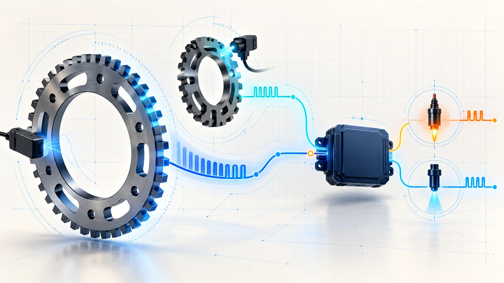
The 6.2L engine needs an accurate time reference before the powertrain control module (PCM) can command fuel and spark correctly. The crankshaft position (CKP) sensor reports crankshaft speed and angular position. The camshaft position (CMP) sensors identify camshaft position and cylinder phase. Together, these signals let the PCM synchronize ignition and sequential fuel injection, recognize engine speed during cranking, and monitor whether combustion events occur where expected.
The linked STEP guides use the 2011-2022 Ford F-250 Super Duty 6.2L gasoline educational grouping. The detailed OEM evidence reviewed for this overview comes from the exact 2011 F-250 4WD Super Duty 6.2L application. Confirm the VIN, engine, calibration, sensor arrangement, wiring diagram, connector information, and current service procedure before testing. Exact circuit design, scan-data names, thresholds, test values, relearn steps, and repair procedures can differ within the grouped range.
A CKP or CMP code does not automatically condemn a sensor. The PCM may lose usable position information because of a damaged circuit, poor terminal contact, compromised shielding, electrical interference, incorrect sensor installation, physical damage at the target wheel, or a controller-side problem. Mechanical timing concerns can also disturb correlation, but a circuit code still has to be diagnosed according to what the PCM actually detected.
How the main parts work together
- Crankshaft position sensing: The CKP sensor reads a patterned wheel on the crankshaft. The repeating pattern gives the PCM engine speed and crank angle, while a reference feature identifies a known crankshaft position.
- Camshaft position sensing: CMP signals identify camshaft position and help distinguish the compression stroke from the exhaust stroke. That cylinder-phase information allows the PCM to sequence injector and ignition events correctly.
- Target wheels and air gaps: The sensor can only report what its target presents. Bent, damaged, loose, contaminated, or incorrectly positioned parts can create a weak, missing, or irregular signal even when the sensor and wiring are electrically intact.
- Power, return, signal, and shielding paths: Depending on the sensor design and application, reliable operation depends on the correct supply or bias, return path, signal circuits, terminal contact, routing, and protection from electrical noise.
- PCM interpretation: The PCM evaluates signal presence, timing, speed, and agreement. It uses that evidence for starting, fuel and ignition control, misfire monitoring, and fault detection.
Why both crank and cam information matter
The crank signal is the basic speed and position reference. If that reference disappears while the engine is cranking, the PCM may show no engine-speed activity and may be unable to start the engine. A valid crank signal alone, however, does not always establish which cylinder is on its compression stroke.
The cam signal supplies that phase information. With crank and cam evidence together, the PCM can identify the correct cylinder event, synchronize sequential injection, and command the intended ignition coil. A CMP fault may therefore produce a different symptom pattern from a total CKP loss. The exact 2011 source evidence supports crank/no-start, hard or extended starting, rough or intermittent operation, inactive cranking RPM, and MIL or code evidence. Confirm any additional behavior against current service information for the exact application.
What P0335 and P0340 are telling you
| DTC | Diagnostic category | What it directs you to prove |
|---|---|---|
| P0335 | CKP signal is missing or unusable for the monitored condition | Whether the engine is producing a credible crank-speed/position signal and whether the sensor, target wheel, circuits, shielding, terminals, or PCM path explains its loss |
| P0340 | Applicable bank-1 CMP signal is no longer detected | Whether the correct cam sensor is installed and producing a usable signal, and whether wiring, return, shielding, interference, terminals, or controller interpretation explains the fault |
These codes overlap because the PCM interprets both signals together, but they are not interchangeable. P0335 challenges the primary crank reference. P0340 challenges a cam phase input. When both are present, preserve the original code status and operating conditions before deciding which one is primary. A shared harness problem, damage caused during recent engine work, or electrical interference may explain more than one code.
What the driver or technician may notice
Possible observations include:
- a crank/no-start condition with no engine-speed indication on the scan tool;
- extended cranking before the engine starts;
- rough or intermittent operation;
- a malfunction indicator lamp with few obvious drivability symptoms;
- an engine-speed signal that drops out, becomes erratic, or disagrees with the physical condition;
- a fault that appears after sensor, front-cover, timing, engine, charging-system, or harness work;
- companion cam/crank circuit, correlation, ignition, injector, misfire, charging, or power-supply DTCs;
- a concern that changes with heat, vibration, engine movement, or harness position.
Symptoms help reproduce and classify the fault. They do not identify the failed part.
Common failure categories
1. Open, shorted, or high-resistance circuit
A broken conductor, short to ground or voltage, poor return path, spread terminal, corrosion, moisture, damaged connector lock, or partially seated connector can remove or distort a position signal. A static continuity check may miss a terminal that loses contact only under vibration or engine movement.
2. Sensor failure or incorrect installation
A damaged sensor can fail electrically or produce insufficient output. An incorrectly installed sensor, wrong part, damaged mounting surface, debris, or an application-specific clearance problem can prevent a good sensor from reading its target correctly.
3. Target-wheel or mechanical damage
Damaged, bent, loose, or displaced target features can corrupt the pattern seen by the CKP or CMP sensor. If the fault followed engine, timing, crankshaft, camshaft, or front-cover work, physical inspection deserves early priority. Electrical replacement cannot correct a damaged target.
4. Shielding, routing, or electrical interference
Position signals can be sensitive to electromagnetic noise. Damaged shielding, altered routing, a harness placed near a high-current source, or charging-system noise can create intermittent faults. Inspect how the harness is routed and whether the concern changes when electrical load or engine speed changes.
5. Power, ground, or shared-path fault
Some sensor configurations depend on a supplied voltage; others generate their own signal but still depend on clean signal and return paths. A shared supply or return concern may affect several sensors and set multiple codes. Diagnose shared electrical evidence before replacing multiple components.
6. Mechanical timing or synchronization concern
If signals are present but their relationship is wrong, investigate correlation and mechanical timing with the applicable procedure. Do not use P0335 or P0340 alone as proof that the timing set has moved, and do not assume electrically clean waveforms prove mechanical timing is correct.
7. PCM connector, calibration, or controller fault
Controller replacement belongs near the end of diagnosis. First prove sensor installation, target condition, signal integrity, power and grounds, terminal contact, harness condition, interference control, and the exact test conditions required by the OEM procedure.
A practical diagnostic strategy
1. Preserve the original evidence
Record all module DTCs, status, freeze-frame data, engine speed, battery voltage, temperature, and the complaint conditions before clearing anything. Ask whether the problem began after engine, timing, sensor, charging-system, battery, or harness work.
2. Separate no-crank, crank/no-start, stall, and running faults
These are different diagnostic starting points. A no-crank condition may prevent meaningful position-signal testing. During a crank/no-start, confirm that the battery and starting system can turn the engine normally, then check whether the PCM reports engine speed. No reported speed during normal cranking strongly supports the CKP branch, but it still does not prove the sensor itself has failed.
3. Establish code priority
Address power, ground, communication, shared supply/return, charging-system, and direct circuit faults before interpreting performance or correlation codes. If multiple CMP codes appear, identify the exact bank and sensor called out by the service information.
4. Inspect before disconnecting everything
Check the correct sensor and connector, harness routing, retainers, heat exposure, chafing, oil or water intrusion, shielding, recent repair areas, and accessible target-wheel condition. Document anything disturbed before moving the harness.
5. Compare scan data with physical reality
Use the specified scan data while cranking or running under safe, repeatable conditions. Look for a missing or unstable engine-speed signal, a dropout that coincides with the symptom, and related inputs that fail at the same moment. Preserve evidence from an intermittent event whenever possible.
6. Prove the electrical path with the exact procedure
Use terminal-safe probes and the correct wiring diagram. Follow the applicable sequence for supply or bias, return, signal output, continuity, isolation from ground or voltage, shielding, and intermittent testing. Do not copy resistance, voltage, pin, or connector information from another model year or sensor type.
7. Evaluate signal quality and correlation only when needed
If basic circuit checks pass, a scope can reveal missing pulses, noise, amplitude changes, or dropouts. Capture crank and cam together when the procedure calls for correlation. Interpret the pattern against known-good information for the exact engine and calibration rather than a generic waveform.
8. Repair the proven fault and verify
Repair the terminal, wiring, shielding, routing, mounting, sensor, target, charging-system, mechanical, or controller condition that failed a test. Restore all retainers and heat protection. Perform only the clearing, learned-value reset, profile learning, self-test, or drive procedure required for the exact vehicle. Reproduce the original operating condition and confirm stable signals, normal starting and running, and no returning DTC.
Repair categories
Typical repairs fall into a few groups:
- connector or terminal repair;
- harness repair and restoration of routing or shielding;
- correct installation or replacement of a proven CKP or CMP sensor;
- repair of a damaged or displaced target component;
- charging-system or interference-source repair;
- mechanical timing repair when correlation testing proves it;
- PCM connector, programming, or controller service only after the input path is proven.
Replacing both sensors because both codes are stored skips the diagnostic work that separates a shared cause from two independent failures.
Safety before testing
Support the vehicle correctly if access requires working underneath it. Never rely on a jack alone. Keep hands, loose clothing, leads, and tools clear of belts, pulleys, fans, and other rotating parts whenever the engine can crank or run. Disable fuel or ignition only as directed by the current service procedure, and remember that remote-start or automatic-start features may create unexpected movement.
Allow hot exhaust and engine components to cool. Disconnect or reconnect PCM and sensor connectors only under the conditions specified by the procedure. Use fused test leads where required, do not apply battery voltage to signal circuits, and never force probes into terminals. Secure oscilloscope and meter leads so they cannot contact rotating or hot components.
What not to do
- Do not replace a CKP sensor from P0335 alone.
- Do not replace a CMP sensor from P0340 alone.
- Do not assume a no-start automatically means the timing chain has failed.
- Do not overlook battery condition, cranking speed, charging-system noise, shielding, routing, or shared circuit faults.
- Do not disturb an intermittent harness before recording the original failure evidence.
- Do not copy pins, thresholds, waveforms, or relearn steps from another year or configuration.
- Do not condemn the PCM before the complete sensor and circuit path is proven.
The diagnostic principle to remember
Engine-position diagnosis is a timing-evidence problem, not a sensor-replacement shortcut. First prove that the engine is turning normally. Then prove that the crank and cam targets are intact, the electrical paths are trustworthy, and the PCM receives stable signals in the correct relationship. When those proofs are separated, P0335 and P0340 become useful directions instead of parts labels.