A missing engine-position signal is a diagnostic direction, not a replacement-part order. On the 6.7 Power Stroke, the PCM uses crankshaft and camshaft information to recognize engine rotation and position. A feed, signal, return, connector or sensor problem can interrupt that information before any mechanical fault is established.
This educational overview covers the 2011–2025 Ford F250 Superduty 6.7 Power Stroke Diesel family. Detailed diagnostic evidence was checked on the exact 2011 and 2025 F-250 4WD 6.7L turbo-diesel source configurations. Those endpoints support the high-level signal-diagnosis discussion; they do not prove identical wiring, calibrations, sensors or procedures for every intervening truck. Confirm the vehicle, engine and applicable service information before using connector details, test limits, scan commands or repair instructions.
What crankshaft and camshaft signals do
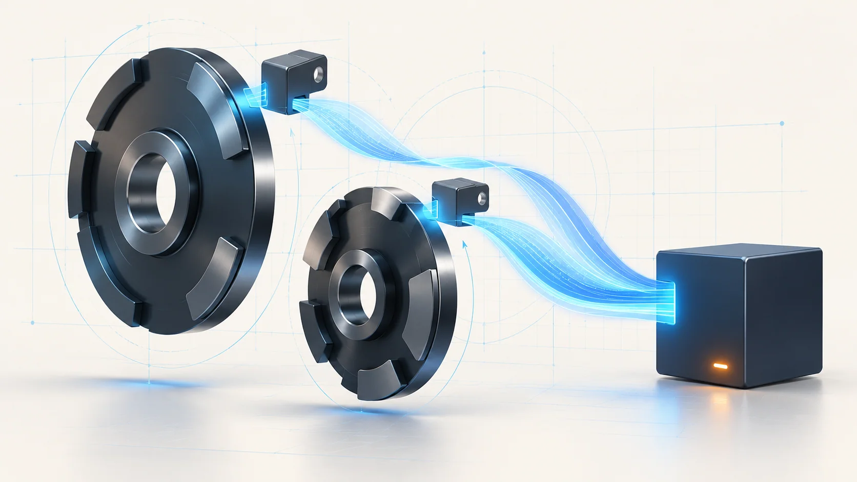
The crankshaft position sensor, usually called CKP, provides the controller with information about crankshaft rotation. The camshaft position sensor, CMP, supplies the corresponding camshaft reference. Together these inputs help the PCM keep its engine-position information aligned. The sensor, its electrical circuits, the physical target it reads and the controller receiving the signal are distinct parts of that information path.
Engine speed and synchronization data are useful observations, but they answer different questions. An RPM reading during cranking indicates that the controller is reporting rotation; it does not independently prove that every part of both position-signal paths is correct. A missing or implausible reading also needs the applicable test context before it can identify a failed component.
The shared diagnostic documents cover several related faults. Their broad headings and shared branches should not be used to infer that every truck has the same variable-timing hardware, target arrangement or mechanical defect.
Two STEP guides, two starting points
**P0335 — Crankshaft Position Signal Performance** addresses a missing expected crankshaft signal. The verified late source describes the PCM recognizing that absence while camshaft rotation information is available. The code can be accompanied by reduced power or a warning. It does not, by itself, prove that the CKP sensor has failed.
**P0340 — P0340 Diagnostic Guide** starts with the PCM detecting no signal from the designated camshaft input. A start or run concern, an intermittent complaint, or a stored code without an obvious symptom may bring the truck into the shop. This is not automatic proof of incorrect base-engine timing.
Use the applicable guide with the complete code set and current symptoms. These links are part of one published vehicle-family library; confirm that a guide's exact test applies to the truck being repaired before following it.
Failure categories to keep separate
Electrical faults include loss of the required feed, an open signal or return path, shorts, damaged terminals and poor connector seating. Harness routing, alterations, shielding and interference can also matter in the camshaft signal diagnosis. A sensor replacement cannot repair an unresolved circuit fault.
The physical sensing path is a separate category. Sensor damage, incorrect installation or misalignment can require inspection when the pinpoint test directs it. The crankshaft path also includes a check for damage to the sensing target. Do not infer an exact target location, tooth pattern or access method from a generic illustration.
The shared camshaft diagnostic material includes base-engine timing and flexplate concerns among possible causes. Their presence in that list does not make either a demonstrated cause of P0340. Enter mechanical branches only when the applicable code and preceding tests direct them. Controller faults remain a later possibility after the relevant circuits, connectors and inputs have been evaluated.
A practical diagnostic strategy
- Establish the complaint. Record codes and available failure context before clearing anything. Separate a current no-start or extended crank from an intermittent stored-code concern, and identify accompanying faults that may change the test path.
- Make cranking observations meaningful. Verify battery condition and starting-system operation as required by the procedure. Compare the scan tool's engine-speed and available synchronization information under the specified conditions. A compromised starting system can undermine the intended test setup.
- Control operating conditions. The verified source procedures warn that diesel regeneration can bias diagnostic values. Follow their direction if regeneration begins; do not interpret readings taken under the wrong conditions as a failed sensor.
- Prove the electrical path. Use the correct diagram and connector views to evaluate the required feed, signal and return circuits. Connected, disconnected, ignition-on and isolated resistance checks are different setups. Do not mix their limits or substitute an assumed ground endpoint.
- Follow the evidence to the next branch. Inspect routing and terminals, then evaluate sensor operation and installation where directed. Reserve target, timing and controller checks for the branches that call for them. A passed static circuit check does not guarantee that an intermittent signal fault is absent.
A scope or other signal test can be useful when the applicable procedure and equipment support it, but this overview supplies no universal waveform, probing point or acceptance limit. Avoid turning a general signal concept into a model-wide test specification.
Repairs, safety and verification
Repairs may involve restoring a damaged circuit, correcting a connector or routing concern, replacing a proven faulty sensor, or correcting an established physical or mechanical fault. Module replacement and any required programming belong to the exact service procedure after the preceding checks; a code alone is insufficient justification.
Keep hands, clothing and test leads away from rotating parts during cranking or running checks. Secure the truck against movement, provide exhaust ventilation, and allow hot exhaust and engine components to cool before access. Use suitable electrical test equipment. Do not improvise jumper connections or perform resistance checks on energized circuits; follow the specified isolation and connection sequence.
After repair, restore every disturbed connection, clear codes or perform resets only as directed, and repeat the prescribed self-test and complaint conditions safely. Check that the relevant signal evidence and original symptoms have been resolved. Some warning behavior may persist until its specified reset conditions are met. Clearing a lamp alone does not demonstrate a completed repair.