A diesel fuel-system complaint can begin with a pressure-control fault, an injector electrical fault or an unreliable sensor input. Those are different diagnostic problems even when the truck has similar symptoms. Replacing a pump or injector before separating them can leave the original concern unresolved.
This overview covers the 2011–2025 Ford F250 Superduty 6.7 Power Stroke Diesel family. Detailed diagnostic evidence was checked on the exact 2011 and 2025 F-250 4WD 6.7L turbo-diesel configurations. The endpoints support a high-level introduction, not identical components or procedures throughout the year range. Sensor assemblies, circuits, scan-tool functions, thresholds and repair instructions must come from the service information applicable to the exact truck.
What the fuel system needs to coordinate
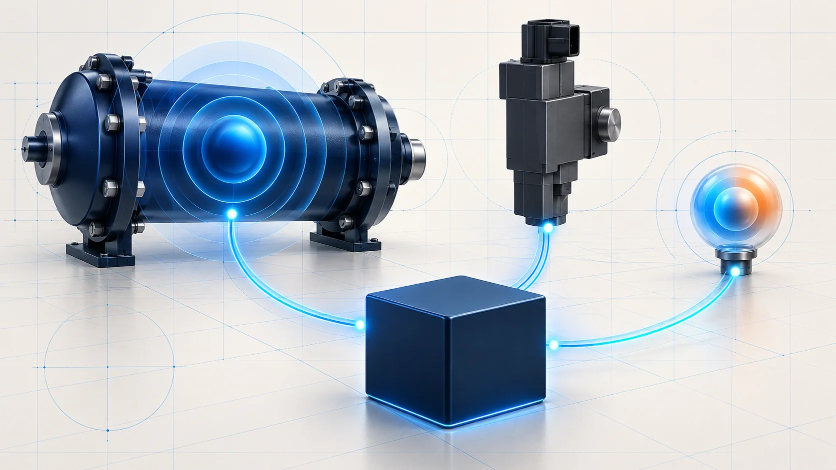
The system must supply fuel, establish the required injection pressure and electrically operate the injectors. The PCM evaluates fuel-system information and commands the relevant controls. Rail-pressure feedback, fuel-pressure and volume-control functions, injector circuits and fuel-temperature information therefore belong to related but distinct diagnostic paths.
Think of pressure as a controlled system condition, an injector circuit as the electrical path used to operate an injector, and temperature as an input that must be believable before it is treated as a physical condition. A pressure fault does not prove a pump failure. An injector circuit code does not prove a blocked nozzle. A high sensor signal does not automatically mean that the fuel itself is hot.
The verified early temperature procedure uses a fuel-rail-temperature sensor context, while the late procedure refers to a fuel pressure and temperature sensor in its diagnostic steps. Do not assume one sensor assembly, connector map or resistance table covers the entire family.
Three guides and the questions they answer
| STEP guide | Diagnostic starting point | What the code alone cannot establish |
|---|---|---|
| P0088 — P0088 Diagnostic Guide | Rail/system pressure is higher than expected for the operating condition. | Which control, feedback or fuel-system component caused it. |
| P0183 — Fuel Temperature Sensor A Circuit High | The PCM detects a fuel-temperature sensor voltage higher than expected. | That actual fuel temperature is excessive, or that the sensor itself has failed. |
| P0201 — P0201 Diagnostic Guide | The cylinder-one injector electrical path needs diagnosis. | Injector flow, spray quality or the need for a complete fuel-system replacement. |
Use these links to select the relevant fault family, then confirm the exact vehicle applicability before using detailed tests. Existing guide titles are retained as published.
Failure categories and possible symptoms
Pressure-control concerns can involve control-valve response, feedback or an established fuel-system condition. The pressure guide discusses reduced power or derate and warning behavior. Symptoms and scan data must be interpreted together; neither a warning nor one pressure observation identifies the failed part.
For an injector circuit concern, consider the harness, connections and injector electrical condition before reaching a controller-side conclusion. The verified early P0201 material includes open or high-resistance wiring and damaged connectors among possible causes. Rough running, reduced power or an intermittent complaint may accompany this fault family, but those symptoms do not distinguish an electrical fault from every other cause of poor combustion.
A temperature circuit concern calls for electrical and input-plausibility checks. Evaluate the sensor signal and return path under the specified conditions. A suspicious temperature reading is evidence to investigate, not permission to infer overheating or immediately replace cooling components. The appropriate code branch controls whether a cooling-system inspection is relevant.
A diagnostic strategy that preserves the branches
- Record the evidence first. Identify the exact truck and collect the complete code set, available freeze-frame data and the complaint conditions. Separate an active no-start or rough-running concern from an intermittent stored fault before clearing anything.
- Respect electrical priorities. The verified late fuel-system test instructs the mechanic to address injector circuit faults before entering that test. If several fault families are present, use the applicable service flow to decide the order instead of treating every code as an independent failed part.
- Distinguish command, feedback and result. Where the procedure calls for it, compare the commanded condition with the reported response. A scan value is not an independent mechanical measurement, and a commanded change does not by itself demonstrate correct pressure or injector performance.
- Follow the actual entry point. Both verified pressure procedures route P0088 to a designated high-pressure system test. Other complaints can take different branches, including low-pressure supply checks. Do not impose one generic low-pressure-first sequence on every code or copy the early repair decision into the late procedure.
- Use the correct test setup. Injector resistance, circuit isolation and sensor tests have specific connection and ignition conditions. Do not reuse meter endpoints, resistance limits or jumper arrangements from a different configuration. Regeneration can bias diagnostic values; follow the source procedure's direction if it begins during testing.
The high-pressure test requires the appropriate scan-tool setup, cables and adapters. This overview supplies no actuator command, pressure target, injector energizing method or fuel-line disconnection procedure. Those details require the exact service and tool instructions.
Repairs and safe verification
A supported repair may restore a circuit or terminal, replace a proven faulty sensor or injector, correct an established control fault, or address contamination when the diagnostic path confirms it. Finding contamination can change the repair scope; replacing one component without following the applicable contamination procedure may be insufficient. Controller replacement and programming remain later, procedure-directed decisions.
High-pressure diesel fuel can remain pressurized with the engine stopped. Before opening any fuel-system connection, qualified personnel must follow the applicable pressure-relief procedure. Never loosen a high-pressure connection as an improvised diagnostic test or use a hand to search for a leak. Energized injector wiring presents an electric-shock hazard; do not handle exposed terminals or improvise power connections.
Control ignition sources, keep the work area ventilated, prepare for spills and remove fuel residue before returning the engine to service. Keep test leads and clothing clear of moving parts and hot components. Follow the prescribed isolation, cleanliness and protective-equipment requirements.
After repair, restore disturbed connections and complete the specified clearing, reset or learning steps only where required. Repeat the relevant self-test and safely reproduce the original complaint conditions. Confirm that the circuit or pressure evidence has recovered and inspect for leakage as directed before returning the truck to service. Some warning behavior may persist until its specified conditions are met; clearing a lamp alone does not prove the repair.