Applicability basis: Verified vehicle records confirm a Sierra 1500 4WD with a 5.3-liter V8 at both the 2014 and 2018 endpoints. Detailed system and diagnostic evidence was collected for a 2018 Sierra 1500 4WD V8-5.3L. Use this article for system-level orientation; exact pressures, commands, component identifiers, connector details, locations, and service steps must come from the applicable information for the truck being repaired.
What the fuel system must accomplish
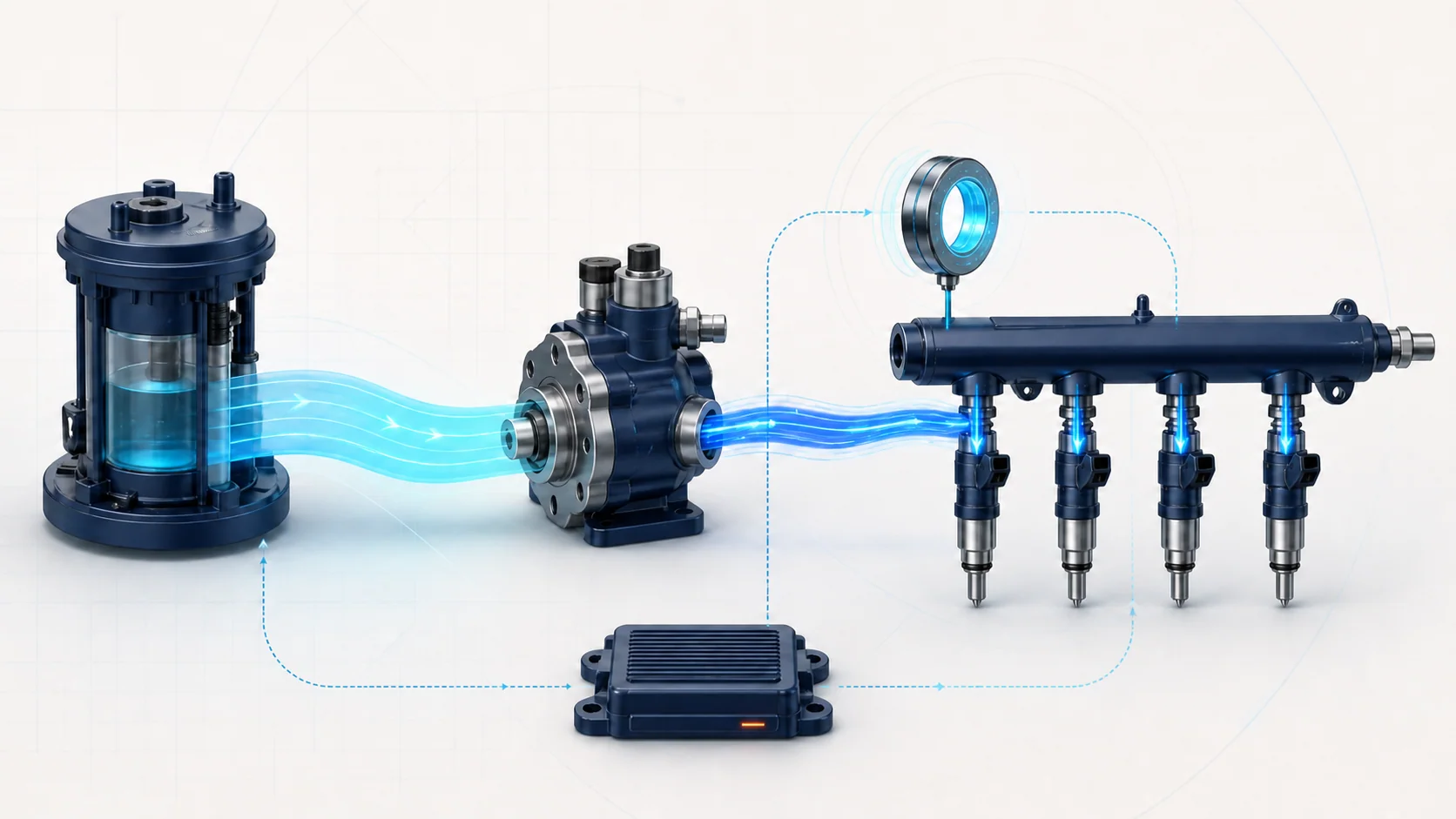
The fuel system has to move gasoline from the tank, create the pressure required by the engine, meter fuel into each cylinder, and give the engine control module enough feedback to judge whether delivery matches its command. On the verified 2018 configuration, those jobs are split between a low-pressure supply stage and a mechanically driven high-pressure direct-injection stage.
The complete control loop has to work:
- the in-tank pump must supply clean fuel at adequate low-side pressure and delivery capacity;
- the high-pressure pump must convert camshaft motion into rail pressure;
- the pump regulator must meter fuel into the high-pressure stage as commanded;
- the rail-pressure sensor must report believable pressure feedback;
- each injector circuit and injector must deliver the commanded amount to its cylinder;
- airflow, oxygen-sensor, ignition, EVAP, exhaust, and mechanical-engine inputs must be believable enough for the controller to evaluate mixture.
A DTC identifies a monitored behavior that did not meet expectation. It does not identify the part that must be replaced.
Main parts of the two-stage system
Confirm the exact arrangement for the truck in front of you. At a useful diagnostic level, the system includes:
- Fuel tank and in-tank pump module: Stores fuel and supplies the low-pressure side.
- Fuel pump driver control module and low-pressure feedback: The controller requests fuel delivery, the pump driver varies pump operation, and pressure feedback helps close the low-side control loop.
- Fuel feed pipe, fittings, and filters or strainers: These carry fuel forward. Restriction, leakage, damage, contamination, or a poor connection can reduce supply.
- Cam-driven high-pressure pump: An engine cam drives the pump piston. A control solenoid or regulator meters fuel so the pump can create the commanded high-side pressure.
- High-pressure rail and rail-pressure sensor: The rail distributes fuel to the injectors, and the sensor reports the pressure the control module uses for monitoring and correction.
- Direct injectors and their control circuits: Each injector meters fuel into one cylinder. The electrical command, injector operation, sealing, and flow all matter.
- Engine control module and mixture feedback: The ECM coordinates pump control and injection, then evaluates rail pressure, fuel trims, exhaust feedback, and cylinder behavior.
The two pressure stages are connected. A high-pressure complaint can begin with inadequate low-pressure supply, while a believable low-side reading does not prove the high-pressure pump, regulator, rail sensor, or injectors are healthy.
How pressure and injection control work together
The in-tank pump moves fuel through the feed circuit to the engine. The verified system uses electronic returnless control: instead of continuously returning warmed fuel from the engine to the tank, the control system varies pump delivery to meet demand.
At the engine, a cam lobe drives the high-pressure pump. The ECM controls the pump regulator while comparing desired fuel pressure with rail-pressure feedback. The rail then supplies the direct injectors. Injection timing and duration determine when and how much fuel enters each cylinder.
This is a feedback system, not a collection of independent parts. If desired and actual pressure separate, the cause may be low-side supply, high-pressure pump drive, regulator control, rail-sensor information, leakage, restriction, injector flow, wiring, or an operating condition outside the fuel system. The code path and supporting data determine which section to test first.
What the related DTCs are telling you
| DTC | Diagnostic category | What it directs you to prove |
|---|---|---|
| P0089 | Fuel-pressure regulator performance | Whether the regulator and high-pressure pump can operate in the expected range after low-side supply, mechanical drive, leakage, restriction, and related circuit or timing prerequisites are checked |
| P0191 | Fuel-rail pressure sensor channel agreement | Whether the redundant pressure outputs inside the fuel pressure and temperature sensor agree; on the exact 2018 source, this is not the general code for actual rail pressure failing to reach a commanded target |
| P0201 | Cylinder 1 injector control circuit open/high resistance | Whether the injector command path is open or has excessive resistance; the code does not by itself prove a restricted, leaking, or failed injector |
| P0171 | Bank 1 lean correction | Why the controller is adding fuel: insufficient delivery is one category, but unmetered air, exhaust leakage, purge flow, sensor error, or combustion problems can produce similar evidence |
These codes overlap, but they do not begin with the same parts decision. P0089 is a regulator operating-range question, P0191 is a redundant sensor-channel agreement question, P0201 is an open/high-resistance injector-control-circuit question, and P0171 is a mixture-result question.
What the driver or technician may notice
Depending on the fault and operating condition, the truck may show:
- a malfunction indicator lamp with little immediate change in drivability;
- extended cranking, hard starting, or a start-and-stall complaint;
- hesitation, reduced power, surging, or poor response under load;
- rough idle, a cylinder misfire, or uneven contribution;
- lean fuel-trim evidence or pressure that cannot follow command;
- fuel odor, visible leakage, or fuel contamination evidence;
- an intermittent complaint that appears only during cold start, hot restart, higher demand, or a particular fuel level.
These are clues, not component tests. A weak low-side supply, restricted line, high-pressure control problem, misleading sensor signal, injector circuit fault, intake leak, purge fault, exhaust leak, ignition fault, or mechanical cylinder problem can produce overlapping symptoms.
Safety before fuel-system testing
Gasoline and gasoline vapor are flammable, and the direct-injection side can retain pressure capable of causing serious skin or eye injury. Eliminate ignition sources, work in a properly ventilated area, wear the required eye and skin protection, and stop if there is uncontrolled leakage.
Do not loosen a high-pressure fitting to see whether fuel is present. Before opening any part of the system, use the depressurization method and fuel-pump-prime precautions specified for the exact truck. A door-opening or other vehicle event may command pump operation on some configurations, so a line that was safe moments earlier can become pressurized again. Capture spilled fuel with approved materials, store contaminated materials correctly, and complete the specified leak check after reassembly.
Common failure categories
1. Low-pressure supply cannot support demand
A weak in-tank pump, poor power or ground, pump-driver control problem, restricted pickup or line, damaged fitting, low fuel level, contamination, or an inaccurate low-side pressure signal can starve the high-pressure pump. The truck may start and idle yet lose pressure when demand rises.
Prove low-side command, electrical supply, pressure, and delivery capacity under the conditions that reproduce the complaint. A static reading at idle may not answer a load-related question.
2. High-pressure generation or regulation is incorrect
The cam-driven pump depends on adequate inlet fuel, sound mechanical drive, correct regulator control, and a sealed high-pressure path. Wear, damage, a sticking regulator, control-circuit fault, internal leakage, restriction, or incorrect mechanical actuation can keep actual rail pressure from following the target.
P0089 does not automatically condemn the high-pressure pump. Verify the low-pressure prerequisite, check related circuit and timing codes, evaluate whether regulator operation remains within the expected range, and follow the applicable isolation path for pump drive, restriction, leakage, or control.
3. Pressure feedback is misleading
On the exact 2018 source, the fuel pressure and temperature sensor contains redundant pressure outputs, and P0191 sets when those two channels disagree. It is not the general diagnostic for actual pressure being too high, too low, or slow to follow command.
Check related reference, data, or circuit DTCs first according to service-information priority. If P0191 remains current after its prerequisites are satisfied, follow the exact P0191 sensor-channel procedure and its repair verification. Use other pressure-performance codes and tests to diagnose genuine pressure-generation faults.
4. An injector circuit cannot deliver the command
P0201 focuses on an open or high-resistance condition in the cylinder 1 injector control path. Terminal problems, harness damage, an open or high-resistance injector winding, or an ECM driver-path fault can prevent the injector from being commanded correctly. Shorts to ground or voltage belong to related injector-circuit DTC categories and should be diagnosed through their own procedures.
An electrically correct injector can still have a mechanical flow or sealing problem, and an injector-circuit code does not prove that fuel pressure is wrong. Keep electrical command testing separate from injector balance, leakage, and mechanical-cylinder testing.
5. Mixture feedback points toward fuel delivery but does not prove it
P0171 means the controller is correcting a lean result on bank 1. Insufficient fuel delivery is only one category. Unmetered intake air, abnormal EVAP purge, an exhaust leak ahead of the relevant sensor, biased airflow or oxygen-sensor data, ignition misfire, and mechanical engine condition can all affect fuel-trim evidence.
Use short- and long-term trim patterns, operating conditions, pressure data, and related DTCs to decide whether the problem is bank-specific, load-sensitive, idle-sensitive, or common to the engine before opening the fuel system.
6. Contamination, leakage, or incorrect fuel changes the result
Water, debris, incorrect fuel, deteriorated fuel, restricted passages, external leakage, or injector leakage can change pressure and combustion behavior. Treat a fuel sample, leak, or contamination finding as evidence to be confirmed and corrected; do not continue electrical or command tests while an active fuel hazard remains.
A practical diagnostic strategy
Step 1: Confirm the exact truck and preserve evidence
Verify model year, engine, drivetrain, fuel type, and calibration-relevant configuration. Record confirmed, pending, and history DTCs plus freeze-frame or failure-record data before clearing anything. Note cold-start, hot-restart, idle, load, fuel-level, and recent-repair conditions.
Step 2: Make the system safe before disturbing it
Inspect for visible leakage without touching or loosening high-pressure connections. If the procedure will require opening the system, follow the exact pressure-relief and pump-prime-disable steps first. Do not substitute a generic method from another year or engine.
Step 3: Classify the complaint
Decide whether the primary evidence is:
- pressure control that cannot follow command;
- pressure feedback that is not believable;
- one injector control circuit that cannot operate;
- a lean mixture result;
- a starting, stall, power, or misfire symptom without a decisive fuel DTC.
This classification prevents every complaint from becoming a high-pressure-pump replacement.
Step 4: Resolve related primary faults first
Follow service-information priority for pump-control, pressure-sensor circuit, voltage, crank/cam correlation, airflow, oxygen-sensor, purge, or injector-circuit DTCs. Performance diagnosis depends on trustworthy commands, inputs, and feedback.
Step 5: Inspect the low-pressure supply path
Check fuel level and quality, recently disturbed connections, accessible pipes and fittings, electrical connectors, harness routing, and evidence of leakage or restriction. Verify low-side operation with the specified scan data and test equipment under the conditions that reproduce the fault.
Step 6: Compare command with feedback
Graph desired and actual rail pressure together when the applicable tool supports it. A stable offset, slow response, sudden dropout, implausible spike, or failure only during higher demand points to different test branches. Do not treat one snapshot as proof of a failed pump or sensor.
Step 7: Separate regulator performance from sensor-channel faults
For P0089 or another pressure-performance complaint, use the applicable procedure to evaluate low-side supply, regulator operating range, mechanical pump drive, leakage, restriction, and pressure response. For P0191 on the exact verified target, diagnose disagreement between the redundant pressure-sensor outputs rather than treating the code as proof that mechanical rail pressure is wrong. Related circuit or data DTCs can require their own electrical paths.
Step 8: Test injector electrical and mechanical behavior separately
For P0201, prove power, control, terminal condition, circuit integrity, and injector electrical behavior before condemning the injector or ECM. If the circuit passes but the cylinder still contributes poorly, move to the specified balance, leakage, ignition, compression, and mechanical tests.
Step 9: Use fuel trims as a direction, not a verdict
Evaluate trim at idle and under controlled load, compare banks where applicable, and check whether pressure behavior changes with the same event. A problem strongest at idle may point toward unmetered air or purge; a problem that grows with load may direct attention toward delivery capacity. Confirm with the applicable test rather than relying on the pattern alone.
Step 10: Repair the proven fault and verify the complete system
The repair may involve an electrical connection, damaged line, low-pressure pump or its control, high-pressure pump regulator or mechanical drive, pressure sensor circuit, injector circuit, injector, contamination correction, intake or purge leak, exhaust leak, ignition fault, or mechanical-engine repair. Follow the exact removal, sealing, fastener, one-time-use-part, and leak-check requirements.
After repair, restore every connection and shield, perform required resets or learns, and compare pressure, fuel trims, cylinder behavior, and pending-code status under the original failure conditions. A cleared code or an incomplete monitor is not repair verification.
Avoid the fuel-system parts cannon
The same pump, regulator, rail sensor, injectors, wiring, and feedback data appear in several code paths, but the failed behavior differs. Make each test answer one question:
- Is low-pressure supply adequate under the complaint condition?
- Does desired rail pressure match the operating state?
- Is actual pressure mechanically wrong or only reported incorrectly?
- Can the regulator and high-pressure pump respond to command?
- Can the injector circuit carry the command?
- Does the injector flow and seal correctly?
- Do mixture and cylinder data support a fuel-delivery fault rather than air, exhaust, ignition, purge, or mechanical causes?
Once the failed section is proven, use the linked STEP guide for model-specific educational context and the applicable service information for exact specifications, connector details, commands, repair steps, and verification.
Final takeaway
On the verified 2018 GMC Sierra 1500 5.3 Gas configuration, low-pressure electronic supply feeds a cam-driven high-pressure direct-injection system. The ECM coordinates pump delivery, pressure regulation, rail feedback, and injector command, then evaluates the combustion result through mixture and cylinder data.
P0089, P0191, P0201, and P0171 describe different failed behaviors. Preserve the evidence, make the system safe, classify the code, prove low-side supply, separate regulator performance from redundant sensor-channel faults, and test injector command separately from injector flow. That sequence turns a broad fuel complaint into a small set of testable sections before parts are replaced.