A misfire code reports uneven combustion, not a shopping list of ignition parts. On the GMC Sierra 1500 5.3 gas engine, spark delivery is one part of a larger system that also depends on air, fuel, compression and correctly interpreted engine-position signals. Separating a combustion problem from an ignition-control circuit fault makes diagnosis more useful and helps avoid unnecessary coil replacement.
This overview covers the conventional 2014–2018 GMC Sierra 1500 5.3 gas configuration. It does not cover eAssist electrical service or establish that every build uses identical wiring, calibrations or test procedures. Engine-specific information at the range endpoints supports the general explanation; the exact year, engine identification and equipment determine the applicable service procedure. Connector assignments, cylinder identification, monitor conditions, test limits and repair specifications must come from that procedure.
What the ignition system does
The ignition system creates a high-energy spark at the right point in the cylinder's operating cycle. The engine control module uses crankshaft and camshaft position information to coordinate spark timing and sequence. The crankshaft signal describes rotation and speed; camshaft information helps distinguish the cylinder's place in the cycle.
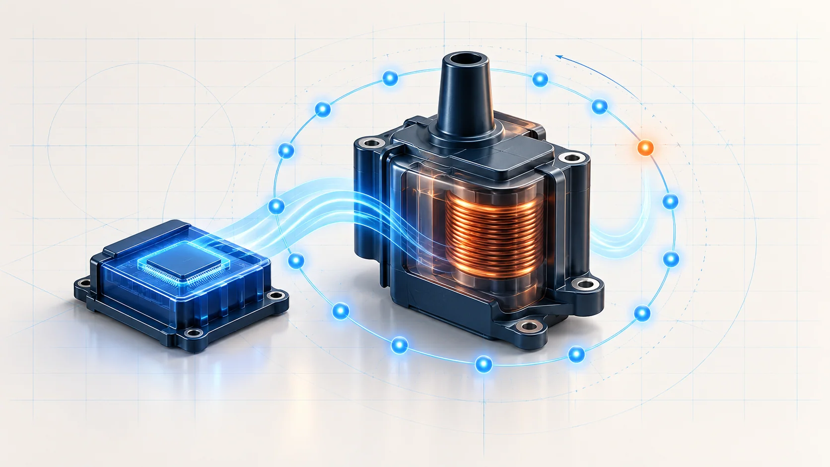
Individual ignition coils receive electrical power and ground and respond to control signals from the engine control module. Each coil includes an electronic driver. Building and interrupting current in its primary winding produces the high voltage needed on the secondary side. The spark must then reach the plug through an intact secondary path with appropriate insulation.
This divides the ignition concern into useful layers: a valid timing reference, a healthy supply and ground, a functioning control circuit, a coil that produces output, and a secondary path that delivers it. A fault in one layer can resemble a fault in another. A coil-control code and a misfire counter therefore provide different evidence.
How the truck recognizes a misfire
The control module evaluates changes in crankshaft rotational speed associated with cylinder events. It does not directly look inside the combustion chamber. Camshaft information helps it associate events with cylinders, while the diagnostic strategy must account for disturbances that are not caused by poor combustion.
Rough-road input and other vibration can complicate interpretation. That does not make a stored misfire code meaningless; it means the evidence needs to be checked against the actual running condition and the applicable diagnostic path. Abnormal mechanical noise also deserves attention rather than being dismissed as an ignition fault.
Severe misfire can overheat and damage the catalytic converter. A flashing malfunction light is a warning to reduce load and stop safely, not an invitation to keep driving until a code becomes permanent. Arrange diagnosis or recovery if severe rough running continues. Do not repeatedly reproduce a damaging condition merely to collect more data.
Two diagnostic categories in the STEP library
| STEP guide | What the evidence means | What it does not prove |
|---|---|---|
| P0300 — random or multiple-cylinder misfire | The monitor has detected a misfire pattern; cylinder counters and operating conditions help focus the investigation. | It does not prove that every cylinder is misfiring, that the cause is ignition, or that a coil or plug must be replaced. |
| P0351 — ignition-coil control-circuit guide | Directs attention to the relevant coil-control electrical path and its diagnostic status. | It is not a verdict on the coil alone. Supply, grounds, terminals, wiring and the module-side circuit need the applicable checks. |
Use the full code description and exact vehicle information to select the circuit. Do not infer a connector pin, a physical coil location or a cylinder assignment from a generic code label or an illustration.
Main failure categories
- Spark delivery: damaged or contaminated insulation, worn or damaged spark plugs, a secondary connection problem, or inadequate coil output can disrupt ignition.
- Electrical control: a poor feed or ground, damaged terminal, open circuit, excessive resistance or a short can affect the coil's operation. A wiring fault can be intermittent with heat, vibration or movement.
- Fuel and air: incorrect fuel delivery, contaminated fuel, an injector concern, unmetered air or a crankcase-ventilation leak can cause poor combustion even when the ignition system works.
- Mechanical and exhaust: compression, valve-train or other mechanical faults and exhaust restriction can produce a misfire complaint. The misfire code does not determine which mechanical component failed.
- Signal interpretation and operating conditions: position-signal concerns, vibration and an intermittent event outside the present test conditions can change the evidence available in the bay.
These categories are possibilities, not claims about which failure is most common on every Sierra in the range.
Symptoms and scan-tool evidence
The driver may report shaking, a rough idle, hesitation, reduced power or a warning light. A fault can appear only on a cold start, after warming up or under load. Record that pattern before changing the vehicle's state: warming an engine can remove the cold-start conditions needed to reproduce the original complaint.
Preserve freeze-frame and failure-record information before clearing codes. Review other relevant faults rather than treating the misfire entry in isolation. Compare current cylinder misfire counters under suitable conditions and use the applicable cylinder-contribution test when needed. A contribution imbalance identifies a cylinder that needs investigation; it does not identify the failed part.
For an electrical coil complaint, the available high, low and open control-circuit test-status data provide another layer of evidence. A status of “Not Run” is not proof that a monitor passed. Similarly, counters that are quiet during a brief idle test do not rule out a fault that occurs only under different conditions.
A practical diagnostic strategy
- Confirm the vehicle and the event. Establish the exact engine and equipment, symptoms, operating conditions and repair history. Preserve codes and event data. If severe misfire or abnormal mechanical noise is present, protect the engine and catalyst before continuing.
- Separate circuit faults from combustion results. Follow relevant electrical or position-signal diagnostics where directed. Keep the coil-control evidence distinct from the misfire monitor's conclusion.
- Locate the pattern without guessing the cause. Use suitable counter and contribution data to distinguish a repeated cylinder concern from a broader pattern. Reproduce the original condition only when safe and required by the procedure.
- Inspect the plausible common causes. Look for damaged connections, insulation contamination, intake or ventilation leaks, fuel concerns and signs of mechanical trouble. Do not skip a mechanical branch just because a misfire code is stored.
- Test the relevant layer. For a coil-control fault, complete the applicable circuit checks before the coil component test. For a combustion fault, separate spark delivery, fuel delivery and mechanical condition using the prescribed tests. A good spark observation does not prove correct fuel delivery or compression.
- Use comparison tests only when appropriate. A permitted component comparison can help localize a fault, but the setup, cylinder identification and interpretation must be correct. Do not substitute random parts swapping or an improvised jumper for the diagnostic procedure.
- Verify more than a cleared code. Recheck the affected circuit status, running quality and misfire data under the relevant conditions. Follow the applicable repair-verification and catalyst checks. If a procedure requires a variation learn or another service function, establish its prerequisites and use the exact vehicle instructions; it is not a universal cure for rough running.
Repair categories and workshop safety
The supported repair may involve wiring or terminals, a verified coil or secondary-ignition fault, the correct spark plug service, fuel or air-system repair, or engine mechanical work. A module replacement requires the complete applicable diagnosis; a code naming a circuit is not enough. Use the specified parts, tightening information and any required setup procedures for the actual vehicle.
Ignition output can cause injury. Use the approved type of spark tester and insulated, properly rated equipment; do not hold a plug wire or create an exposed spark near fuel. Turn the vehicle off before disconnecting components as directed, and keep hands and leads clear of belts, fans and hot exhaust parts. Never probe a control-module circuit with an improvised load or bridge terminals based on an overview.
Fuel testing has separate pressure-relief and fire precautions, particularly on a direct-injection engine. Do not loosen a fuel connection as a quick injector test. Provide exhaust extraction for running tests. If verification requires driving, use safe data recording or another technician rather than watching scan data while driving.
The goal is a coherent chain of evidence: confirm the misfire, identify the affected operating condition and cylinder pattern, prove the faulty system layer, and demonstrate that the repair corrected it. Neither the code name nor the newest part in the bay replaces that chain.