A camshaft-related code does not automatically mean that a position sensor failed. On an Accord, the diagnostic question may involve camshaft phase, an oil-operated valve-control mechanism, or the electrical circuit that commands or monitors it. Those are connected systems, but they require different evidence.
This introduction covers the 2010-2017 Honda Accord 2.4 Gas vehicle family. The operating and diagnostic examples were reviewed against a 2017 Accord Sedan 2.4-liter configuration, including the USA/Canada rocker-arm pressure-switch arrangement. The range spans different model generations and engine configurations. It does not establish identical hardware, DTC coverage, wiring, or repair procedures for every year or market. Identify the actual vehicle before applying its service information.
Three functions to keep separate
Mechanical timing establishes the relationship between crankshaft rotation and camshaft operation. In the reviewed diagnostic path, camshaft timing and cam-chain condition are separate things to inspect when a phase problem has been demonstrated. A phase-related code is a reason to investigate that relationship, not proof that the chain has stretched.
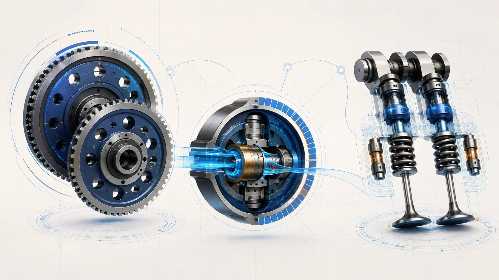
Variable Timing Control (VTC) changes when the intake valves operate by advancing or retarding the intake camshaft. In the reviewed 2017 system, the PCM commands an oil-control solenoid that directs oil pressure to the VTC actuator. The actuator changes camshaft angle, while camshaft-position feedback helps the PCM regulate the result. This is continuous phasing, not simply an on/off high-lift mode.
VTEC changes the intake valve-lift mode. In the reviewed system, the PCM uses operating information such as engine speed, load, throttle position, and temperature to control the rocker-arm oil solenoid. Oil pressure operates switching pistons in the rocker-arm mechanism so the valves follow the appropriate low- or high-lift cam profile. Do not treat the VTEC solenoid and the VTC oil-control solenoid as interchangeable names for one component.
Both control systems depend on electrical commands and hydraulic action. That does not mean every associated DTC is an oil-pressure fault, or that topping up oil resolves every control problem.
Commands, movement, and feedback are different evidence
For VTC, a requested camshaft angle and the observed camshaft response are different pieces of information. An electrical command does not by itself prove that the oil-control valve, actuator, and mechanical timing can produce the expected result. Conversely, a phase error alone does not identify which of those elements is responsible.
For the reviewed USA/Canada VTEC arrangement, the rocker-arm oil-pressure switch reports the hydraulic-pressure condition associated with the switching system. It is not a substitute for a general engine lubrication-pressure measurement. Its wiring and switching behavior also matter: a high-voltage circuit code must not be translated into a conclusion that physical oil pressure is too high.
There is also a control-system interaction worth remembering. The reviewed 2017 description states that a VTEC malfunction can disable VTC control and hold timing at the fully retarded position. A lack of normal VTC movement therefore needs to be interpreted alongside companion codes and the applicable control conditions, not automatically diagnosed as a seized actuator. Confirm this behavior in the actual vehicle's service information before applying it to another year.
How the three STEP guides fit together
These guides belong to this vehicle family. Use the applicable vehicle-specific procedure for the exact tests and repair sequence.
| STEP guide | Diagnostic question | Avoid this shortcut |
|---|---|---|
| P0341 - incorrect cam/crank phase | Does the observed phase relationship pass the required checks, and do VTC control, mechanical timing, chain condition, and actuator operation explain a failure? | Replacing a camshaft sensor or timing chain solely because its name appears in the code discussion. |
| P2647 - rocker-arm oil-pressure switch circuit high voltage | After code priority and oil level are addressed, does the switch circuit provide the expected response? | Assuming that circuit high voltage proves excessive oil pressure or a failed switch. |
| P2649 - rocker-arm oil-control solenoid circuit | Is the solenoid winding and its ground/control path intact under the prescribed test conditions? | Treating an electrical control fault as proof of a mechanically failed valve train. |
For the reviewed code combination, P2649 takes priority over P2647 when both are stored. Follow that order before evaluating the pressure-switch complaint. This is a specific diagnostic dependency, not a universal rule to sort all codes numerically.
Symptoms and possible failure categories
The driver may report a warning light or a change in engine response. An intermittent fault may leave the engine apparently normal during the workshop visit. Neither normal behavior at that moment nor the absence of an immediately returning code proves that the required monitor has completed successfully. These clues guide the investigation; they are not a guaranteed symptom list or evidence of how often a part fails.
Keep four broad categories in mind:
- Oil supply and hydraulic control: establish the correct oil level where the procedure calls for it, then evaluate the relevant control function. An acceptable level is not proof of correct pressure or actuator operation.
- Electrical control and feedback: a solenoid winding, open ground or control wire, pressure-switch circuit, or poor terminal connection can interrupt the system without proving mechanical damage.
- Mechanical timing and actuation: incorrect camshaft timing, a damaged or stretched chain, or a faulty VTC actuator belong in the investigation when the prescribed checks point there.
- Intermittent conditions and control state: captured operating conditions, connectors, and whether the function is enabled can explain why today's response differs from the original event.
A practical diagnostic approach
First, save pending and confirmed codes, freeze-frame information, and available snapshots before clearing anything. Record the complaint and recent repair history. Check current service information and relevant bulletins, then identify companion-code priorities for the actual configuration.
Next, choose the right branch. For a P2647 complaint, the reviewed path includes an oil-level check and a VTEC function check before switch-circuit isolation. For P2649, the evidence progresses through the solenoid's electrical condition and its ground and control paths. Use the specified connector state and equipment; a reading taken under different conditions may answer the wrong question.
For P0341, distinguish a demonstrated failure from a test that has not yet run. The reviewed path can require VTC functional and monitor checks even when the code does not immediately return. If it directs further investigation, it separately evaluates the VTC oil-control valve, camshaft timing, chain condition, and actuator. Preserve those distinctions instead of replacing the entire timing system as a group.
Do not force a non-reproduced intermittent fault through a failed-test branch. At the same time, do not stop early when the applicable procedure still calls for a functional check or completed monitor. Document what actually passed, failed, or remained incomplete.
What a justified repair looks like
The repair should match a demonstrated defect: correct the oil level, restore a proven wiring or terminal fault, replace a failed switch or oil-control component, or perform the directed mechanical timing repair. Chain and actuator work require the correct inspection and service procedures; this overview does not provide alignment marks, disassembly steps, or replacement criteria.
PCM software or module substitution is a late, procedure-directed decision in the reviewed electrical paths. It is not a substitute for establishing the solenoid, switch, wiring, and connection condition first.
Safety and repair verification
Keep the engine off for service work unless the applicable test specifically requires it to run. Allow hot engine parts to cool, keep hands and clothing away from moving components, provide exhaust ventilation during running tests, and securely support the vehicle whenever access underneath is required. Use appropriate eye protection and stop if the required equipment or training is missing.
Follow the specified controller-shutdown and connector-handling instructions before electrical isolation. Do not force probes into terminals, pierce insulation, or improvise jumpers. Internal timing work should follow the complete vehicle-specific service procedure, not a conceptual illustration or this overview.
After the repair, restore disturbed connections and complete the required reset, idle-learning, or crankshaft-pattern-learning operations only as directed. These are not interchangeable with simply clearing codes, and they do not replace a needed mechanical repair.
Finally, verify the relevant function and follow the code-specific post-repair checks. Where monitor status is used, require a completed passing result; an incomplete monitor is not a pass. Check for returning and additional codes. The goal is to prove the corrected phase, hydraulic-control response, or electrical circuit behavior that justified the repair.